|
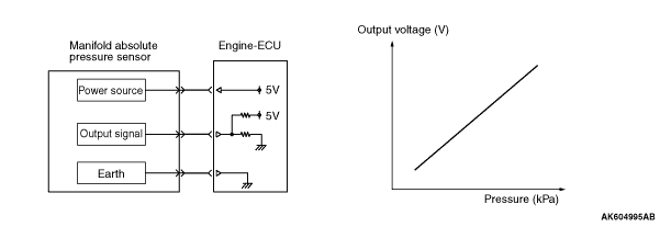
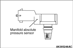
Manifold absolute pressure sensor is installed in inlet manifold. Manifold absolute pressure
sensor uses a piezo resistive semiconductor to output the voltage according to manifold absolute
pressure to engine-ECU. Engine-ECU uses this output voltage and engine speed to calculate fuel
injection volume according to manifold absolute pressure. Sensor properties are as shown in the
figure.
|
|
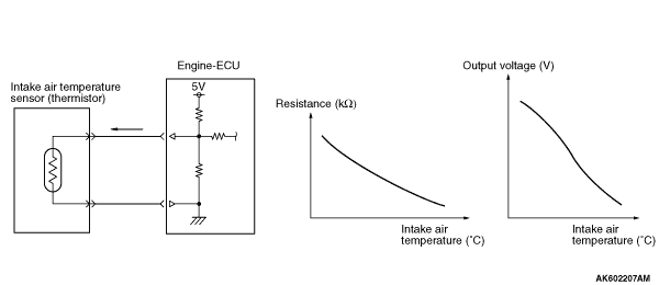
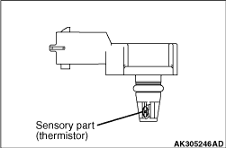
Intake air temperature sensor is built in to the manifold absolute pressure sensor. Intake
air temperature sensor detects intake air temperature through thermistor’s resistance
change and outputs the voltage according to intake air temperature to engine-ECU. Engine-ECU
uses this output voltage to compensate fuel injection control. Sensor properties are as shown
in the figure.
|
|
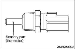
Engine coolant temperature sensor is installed on the cylinder head. Engine coolant temperature
sensor uses thermistor’s resistance change to detect coolant temperature and output
the voltage according to coolant temperature to engine-ECU. Engine-ECU uses this output voltage
to appropriately control fuel injection volume, idle speed and ignition timing when the engine
is cold. Sensor properties are as shown in the figure.
|
|
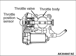
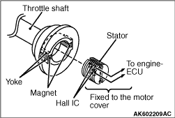
The throttle position sensor is installed in the throttle body. Throttle position sensor
outputs voltage to engine-ECU based on the throttle shaft rotation angle. Engine-ECU uses this
signal to detect the throttle valve opening angle to perform throttle valve control servo feedback
control. This throttle position sensor uses Hall IC and is of non-contact type.
|
|
Throttle position sensor is composed of a permanent magnet fixed on the throttle shaft,
Hall IC that outputs voltage according to magnetic flux density and a stator that efficiently
introduces magnetic flux from the permanent magnet to Hall IC.
|
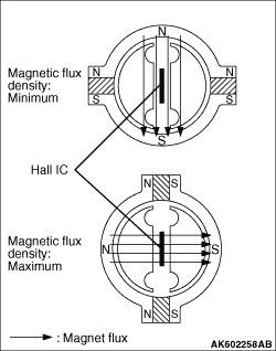
|
Magnetic flux density at Hall IC is proportional to the output voltage.
Throttle position sensor has 2 output systems - throttle position sensor (main)
and throttle position sensor (sub), and the output voltage is output to engine-ECU. When throttle
valve turns, output voltage of throttle position sensor (main) and throttle position sensor
(sub) changes. This allows engine-ECU to detect actual throttle opening angle. Engine-ECU uses
this output voltage for throttle valve control servo feedback control. Also, engine-ECU compares
output voltage of the throttle position sensor (main) and throttle position sensor (sub) to
check for abnormality in the throttle position sensor. The relationship between throttle opening
angle and output voltage of the throttle position sensor (main) and throttle position sensor
(sub) is as shown in the figure below.
|
|
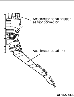
Accelerator pedal position sensor is integrated with accelerator pedal, and detects accelerator
opening angle. Engine-ECU uses the output voltage of this sensor to control appropriate throttle valve
opening angle and fuel injection volume. This accelerator pedal position sensor uses Hall IC
and is a non-contact type.
|
|
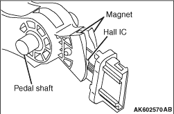
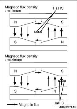
Accelerator pedal position sensor is composed of a permanent magnet fixed on the magnet
carrier of the pedal shaft, Hall IC outputs voltage according to magnetic flux density and a
stator that efficiently introduces magnetic flux from the permanent magnet to Hall IC.
|
|
Magnetic flux density at Hall IC is proportional to the output voltage.
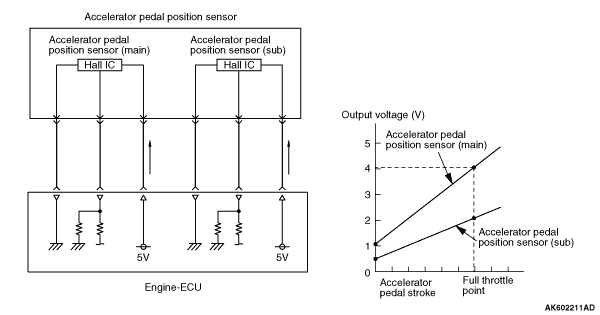
The accelerator pedal position sensor has 2 output systems - accelerator pedal
position sensor (main) and accelerator pedal position sensor (sub), and the output voltage is
output to engine-ECU. According to depression of the accelerator pedal, output voltage of the
accelerator pedal position sensor (main) and accelerator pedal position sensor (sub) changes.
This allows engine-ECU to detect the actual accelerator pedal depression amount. Engine-ECU
uses accelerator pedal position sensor (main) output voltage for appropriate throttle valve
opening angle control and fuel injection volume control. Also, engine-ECU compares output voltage
of the accelerator pedal position sensor (main) and accelerator pedal position sensor (sub)
to check for abnormality in sensor. The relationship between accelerator opening angle and output
voltage of the accelerator pedal position sensor (main) and accelerator pedal position sensor (sub)
is as shown in the figure below.
|
|
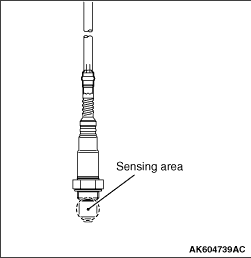
Depending on the vehicle, the installation location
of the oxygen sensor is as follows.
<M/T>
Oxygen sensors are installed in front and rear of the catalytic converter.
<A/T>
Oxygen sensor is installed in front and rear of the catalytic converter within the front
exhaust pipe.
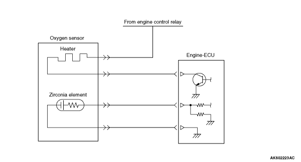
Oxygen sensor has a built-in heater to help early activation of the sensor. This allows
feedback control of air-fuel ratio soon after the engine start.
|
|
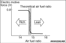
This sensor uses the oxygen concentration cell principle of solid electrolyte (zirconia)
and displays the property of sudden change in output voltage near theoretical air-fuel ratio.
This property is used to detect oxygen density in exhaust gas. Feedback to engine-ECU allows
it to judge whether air-fuel ratio is rich or lean compared to theoretical air-fuel ratio.
|

|
This allows engine-ECU precise feedback control to get theoretical air-fuel ratio with
best cleaning efficiency of 3-way catalytic converter.
|
|
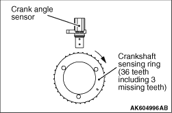
A crank angle sensor is installed on the inlet side of the cylinder block. The crank angle
sensor monitors rotation of crankshaft sensing ring (36 teeth including 3 missing teeth) installed
on the crankshaft and converts to voltage (pulse signal) that is output to engine-ECU. Engine-ECU
uses crank angle sensor’s output pulse to detect crank angle.
|

|
The crank angle sensor uses a magnetic resistance element. When the vane of the crankshaft
sensing ring passes the front surface of the magnetic resistance element, the flux from the
magnet passes the magnetic resistance element. Thus, resistance of the magnetic resistance element
increases. When the vane of the crankshaft sensing ring does not pass the front surface of the
magnetic resistance element, the flux from the magnet does not pass the magnetic resistance
element and the resistance decreases. The crank angle sensor converts this change in resistance
of the magnetic resistance element to a 5 V pulse signal and outputs it to engine-ECU.
|

|
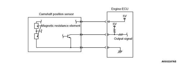
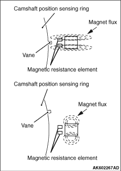
A camshaft position sensor is installed on the inlet of the cylinder head. The camshaft
position sensor monitors rotation of the camshaft position sensing ring (6 teeth) and converts
to voltage (pulse signal) that is output to engine-ECU. Upon receiving this output voltage,
the engine-ECU effects feedback control to optimize the phase of the camshaft. Engine-ECU uses
a combination of the camshaft position sensor output pulse signal and crank angle sensor output
pulse signal to identify cylinders in the compression process.
|
|
The camshaft position sensor uses a magnetic resistance element. When the vane of the
camshaft position sensing ring passes the front surface of the magnetic resistance element,
the flux from the magnet passes the magnetic resistance element. Thus, the resistance of the
magnetic resistance element increases. When the vane of the camshaft position sensing ring does
not pass the front surface of the magnetic resistance element, the flux from the magnet does
not pass to magnetic resistance element and resistance decreases. The camshaft position sensor
converts this change in resistance of the magnetic resistance element to a 5 V pulse signal
and outputs the signal to engine-ECU.
|
|
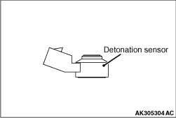
A detonation sensor is installed on the inlet side of the cylinder block. Detonation sensor
uses the piezoelectric element to convert the vibration of the cylinder block generated when
engine is in operation to minute voltage that is output to engine-ECU. Engine-ECU uses the minute
output voltage from the detonation sensor filtered through the cylinder block’s natural frequency
to detect knocking, and compensates the ignition timing lag according to the strength of the
knocking.
|
|
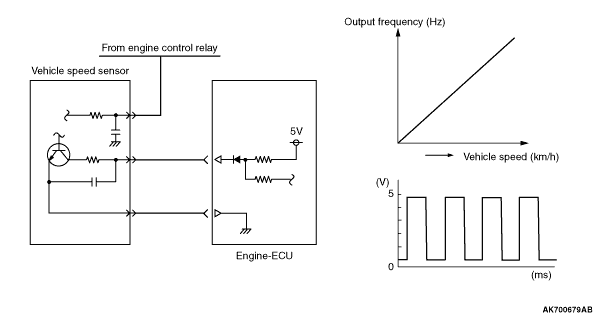
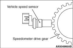
A vehicle speed sensor is installed on the transmission. The vehicle speed sensor uses
Hall IC. The vehicle speed sensor monitors rotation of the speedometer drive gear installed
on the differential case and converts to voltage that is output to engine-ECU. Engine-ECU calculates
vehicle speed based on the vehicle speed sensor’s output frequency. Sensor properties are
as shown in the figure.
|
|
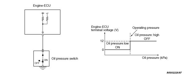
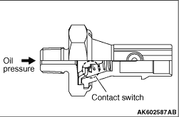
The oil pressure switch is installed on the inlet side of the cylinder block. The oil
pressure switch detects whether the oil pressure is high or low using the contact switch. When
the oil pressure becomes higher than the specified value after the engine starts, the contact
point of the oil pressure switch opens.
This allows the engine-ECU to detect the oil pressure is higher than the specified value.
The engine-ECU outputs the OFF signal to the combination meter through the CAN and then turns
off the oil pressure warning lamp.
|
|
|
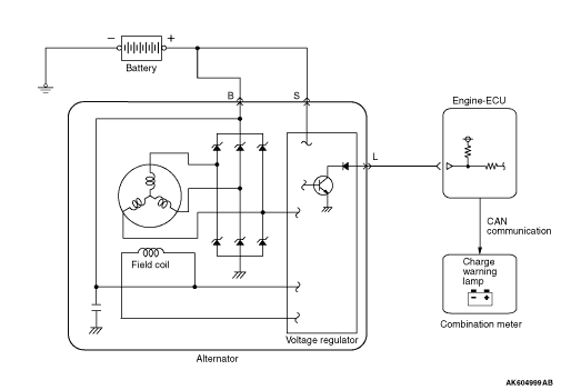
Alternator turns ON/OFF the power transistor in the voltage regulator to adjust current
flow in the field coil according to alternator output current. In this way alternator output
voltage is kept adjusted (to about 14.4 V). The ratio of power transistor ON time (ON duty)
is output from alternator FR terminal to engine-ECU. Engine-ECU uses this signal to detect alternator
output current and drives throttle valve control servo according to output current (electric
load). This prevents change in idle speed due to electric load and helps maintain stable idle
speed.
|
|
|
After turning on the ignition switch, the current is input by the engine-ECU to the alternator
L terminal. This allows the voltage regulator to be on and the field coil to be excited. When the
alternator rotates in this situation, the voltage is excited in the stator coil and the current
is output from B-terminal through the commutation diode. Also the generated voltage is input
to the voltage regulator through the commutation diode. After the electric generation begins,
the current is supplied to the field coil from this circuit. In addition, the generated voltage
is output from the alternator L terminal to the engine-ECU. This allows the engine-ECU to detect
that the electric generation begins. The engine-ECU outputs the ON signal to the combination meter
through the CAN and then turns off the charge lamp.
|