|
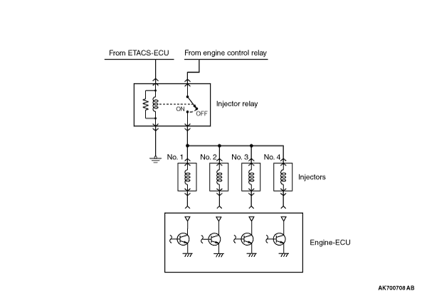
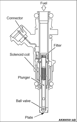
An injector is an injection nozzle with the electromagnetic valve that injects fuel based
on the injection signal sent by engine-ECU. 1 injector is installed in the inlet manifold of
each cylinder and fixed to the delivery pipe. When electricity flows through the solenoid coil,
the plunger gets sucked in. The ball valve is integrated with the plunger, and gets pulled together
with the plunger till the fully open position so that the injection hole is fully open and the
fuel gets injected.
Voltage from the battery gets applied from the injector relay to the injector and up to
the engine-ECU. Engine-ECU turns ON its power transistor and prepares the injector’s
ground circuit. Thus, current flows through the injector while power transistor is ON and the
injector injects fuel.
|
|
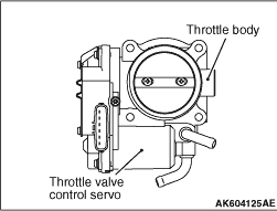
A throttle valve control servo is installed in throttle body. The throttle valve control
servo performs the Open/Close of the throttle valve through the reduction gear. Engine-ECU changes
current direction according to the Open/Close direction and also changes current to the motor
coil to control the throttle valve control servo.
Throttle valve control servo is composed of a good response, low energy, and small DC
motor with brush and can generate rotation force corresponding to the current applied on the
coil. When there is no current passing through the throttle valve control servo, the throttle
valve remains at a prescribed opening angle. So, even if current stops because of a fault in the
system, a minimum level of running remains possible.
|
|
|
Refer to GROUP 16 - Ignition System - Ignition Coil  . .
|
|
|
Refer to GROUP 17 - Emission Control - Evaporative Emission Control
System .
|
|
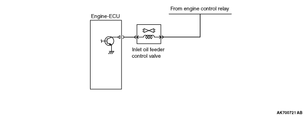
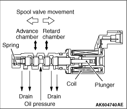
The inlet oil feeder control valve is installed on the inlet side of the cylinder head.
Receiving the duty signal from the engine-ECU, the inlet oil feeder control valve moves the
spool valve position and divides the oil pressure from the cylinder block into the advanced
chamber and the retarded chamber of the V.V.T. sprocket as well as continually changes the inlet
camshaft phase. The spring makes spool valve stop at the position where the inlet camshaft is
at the most retarded angle when the engine is stopped. The engine-ECU moves the spool valve position
by increasing and decreasing ON duty ratio of the inlet oil feeder control valve and allows
the inlet camshaft to be at the target phase angle. When the duty ratio increases, the spool
valve moves. The sprocket rotates toward the advanced angle side. When the duty ratio decreases,
the sprocket rotates toward the retarded angle side. When the medium duty ratio, at which the
spool valve is at the medium position, is achieved, all the oil passages are closed. This allows
the phase angle to be kept constant. The engine-ECU changes and controls the duty ratio in accordance
with the engine operation to get the optimum phase angle.
|
|
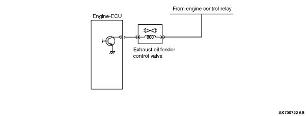
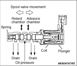
The exhaust oil feeder control valve is installed on the exhaust side of the cylinder
head. Receiving the duty signal from the engine-ECU, the exhaust oil feeder control valve moves
the spool valve position and divides the oil pressure from the cylinder block into the advanced
chamber and the retarded chamber of the V.V.T. sprocket as well as continually changes the exhaust
camshaft phase. The spring makes spool valve stop at the position where the exhaust camshaft
is at the most advanced angle when the engine is stopped. The engine-ECU moves the spool valve
position by increasing and decreasing ON duty ratio of the exhaust oil feeder control valve
and allows the exhaust camshaft to be at the target phase angle. When the duty ratio increases,
the spool valve moves. The sprocket rotates toward the retarded angle side. When the duty ratio
decreases, the sprocket rotates toward the advanced angle side. When the medium duty ratio,
at which the spool valve is at the medium position, is achieved, all the oil passages are closed.
This allows the phase angle to be kept constant. The engine-ECU changes and controls the duty
ratio in accordance with the engine operation to get the optimum phase angle.
|
|
|
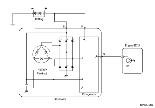
Engine-ECU uses ON/OFF of alternator G terminal to control alternator output voltage.
When the power transistor in the engine-ECU turns ON, output voltage gets adjusted to about
12.8 V. When alternator output voltage drops to 12.8 V it becomes lower than voltage of the
charged battery and almost no current is output from the alternator. When the power transistor
in the engine-ECU turns OFF, output voltage gets adjusted to about 14.4 V. When alternator output
voltage is about 14.4 V, alternator outputs current to produce electricity. In case electric
load is alternator suddenly, engine-ECU controls alternator G terminal’s On-duty to
limit the sudden increase in alternator load due to generation and thus prevents change in idle
speed.
|