GENERAL INFORMATION
<4A9, 4B10>
- Fuel injector
- Fuel delivery pipe
- Fuel vapour canister
- Fuel tank assembly
- Fuel tank pump and gauge assembly
SPECIFICATIONS
| Item |
Specification |
|
| Fuel tank capacity L |
59 |
|
| Fuel pump type |
Electric |
|
| Fuel filter type |
Cartridge (incorporating fuel tank pump and gauge assembly) |
|
| Fuel pump pressure regulator control pressure kPa |
324 |
|
| Fuel injector |
Type |
Elector-magnetic |
| Quantity |
4 |
|
| Evaporative emission control system |
Fuel vapour canister |
|
CONSTRUCTION DIAGRAM

- The quick-joint connector of a plastic tube is used for the fuel delivery pipe joint of fuel high-pressure hoses and for the fuel tank pump and gauge assembly joint of fuel line pipe (main) to reduce the permeation of fuel evaporative emission.
- The surface of underfloor fuel pipes is coated with 1-mm thickness of plastic to improve resistance to corrosion and chipping.
- A returnless fuel system eliminates returned fuel from the engine. The heat that fuel receives from the engine is reduced, minimizing fuel temperature in the fuel tank and controlling the amount of evaporated gas.
- The activated charcoal of fuel vapour canister is modified for downsizing, weight saving and better performance.
- The rubber boots is employed for the filler port mounting part of fuel filler neck to protect fuel filler neck in case of collision.
<4B11-TURBO>
- Fuel injector
- Fuel delivery pipe
- Fuel pressure regulator
- Fuel vapour canister
- Fuel tank assembly
- Fuel tank pump and gauge assembly
- Fuel tank gauge unit
SPECIFICATIONS
| Item |
Specification |
|
| Fuel tank capacity L |
55 |
|
| Fuel pump type |
Electric |
|
| Fuel filter type |
Cartridge (incorporates fuel tank pump and gauge assembly) |
|
| Fuel pressure regulator pressure kPa |
329 |
|
| Fuel injector |
Type |
Electro-magnetic |
| Quantity |
4 |
|
| Evaporative emission control system |
Fuel vapour canister |
|
CONSTRUCTION DIAGRAM

- The quick-joint connector of a plastic tube is used for the fuel delivery pipe joint of fuel high-pressure hoses and for the fuel tank pump and gauge assembly joint of fuel line pipe (main) to reduce the permeation of fuel evaporative emission.
- The surface of underfloor fuel pipes is coated with 1-mm thickness of plastic to improve resistance to corrosion and chipping.
- The activated charcoal of fuel vapour canister is modified for downsizing, weight saving and better performance.
- The rubber boots is employed for the filler port mounting part of fuel filler neck to protect fuel filler neck in case of collision.
<BWC>
- Unit injector
- Tandem pump
- Fuel temperature sensor
- Fuel filter assembly
- Fuel cooler
- Fuel tank assembly
- Fuel tank pump and gauge assembly
SPECIFICATIONS
| Item |
Specification |
|
| Fuel tank capacity L |
59 |
|
| Fuel pump type |
Electric (integrated in fuel tank pump and gauge assembly) |
|
| High-pressure fuel pump type |
Mechanical type |
|
| Fuel filter type |
Cartridge (filter-paper type) |
|
| Fuel injector |
Type |
Electro-magnetic |
| Quantity |
4 |
|
CONSTRUCTION DIAGRAM
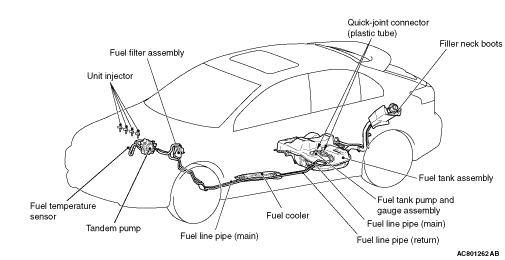
- The surface of underfloor fuel lines is coated with 1-mm thickness of resin to improve resistance to corrosion and chipping.
- The quick-joint connector of a plastic tube is used for the fuel tank pump and gauge assembly joint of fuel line pipe (main) and for the fuel tank pump and gauge assembly joint of fuel line pipe (return) to reduce the permeation of fuel evaporative emission.
- The fuel cooler has been installed to the fuel return line to suppress rise in the fuel temperature inside the fuel tank.
- The rubber boots is employed for the filler port mounting part of fuel filler neck to protect fuel filler neck in case of collision.