Name
|
Function
|
SENSOR
|
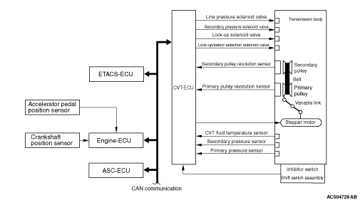
Primary pulley rotation sensor
|
Outputs the primary pulley (input shaft) speed as a pulse signal to CVT-ECU.
|
Secondary pulley rotation sensor
|
Outputs the secondary pulley (output shaft) speed as a pulse signal to CVT-ECU. The pulse signal is converted to the vehicle speed by CVT-ECU.
|
CVT fluid temperature sensor
|
Detects the CVT fluid temperature.
|
Primary pressure sensor
|
Detects the pressure applied to the primary pulley.
|
Secondary pressure sensor
|
Detects the pressure applied to the secondary pulley.
|
Inhibitor switch
|
Detects the selector lever position by the contact-type switch.
|
Shift switch assembly
|
Detects the request in the sport mode by the contact-type switch at the selector lever.
|
Paddle shift switch
|
Detects the operation status of the paddle shift switch.
|