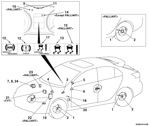
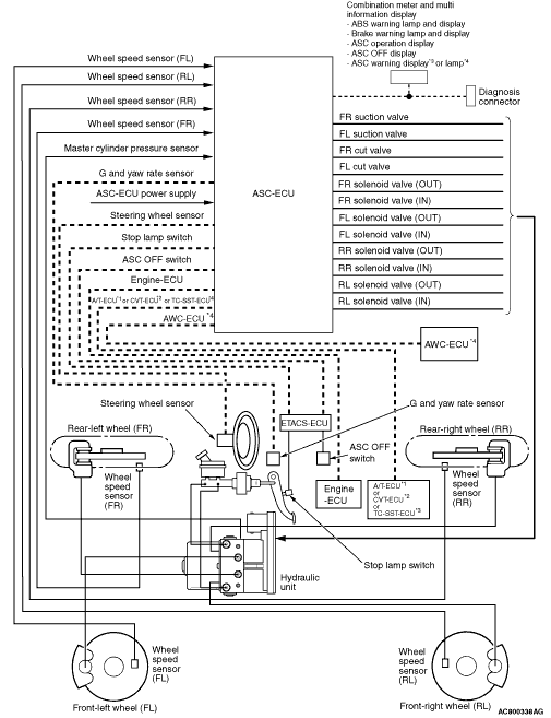
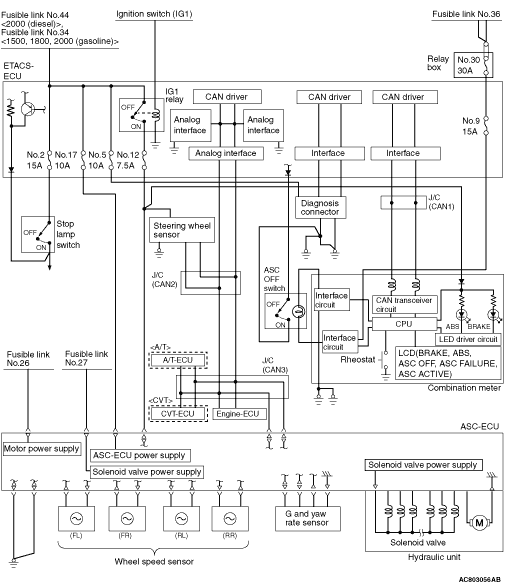
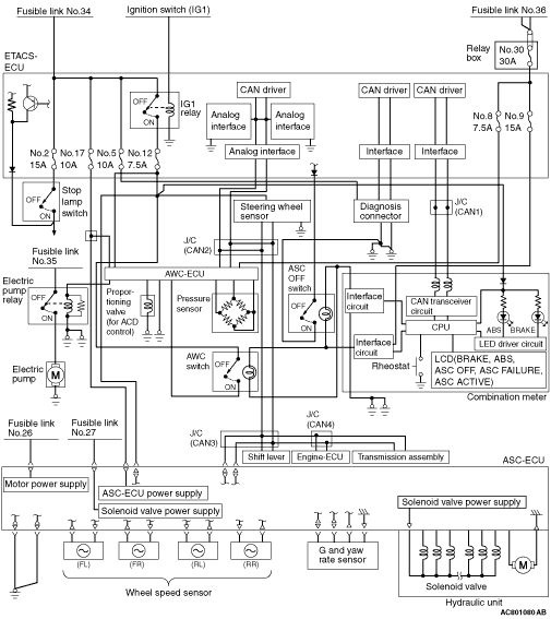
Name of part
|
Number
|
Functional description
|
Sensor
|
Wheel speed sensor
|
1
|
Outputs the frequency signal in proportion to the rotation speed
of each wheel to ASC-ECU.
|
Magnetic encoder for wheel speed detection
|
2
|
The wheel speed sensor is a pulse generator. When the magnetic encoder
for wheel speed detection (a plate on which north and south pole sides of the magnets are arranged
alternately) rotates, it outputs frequency pulse signal in proportion to each wheel speed.
|
Stop lamp switch
|
3
|
Outputs the signal indicating whether the brake pedal is depressed
or not to ASC-ECU.
|
G & yaw rate sensor
|
4
|
Detects longitudinal and lateral acceleration of a vehicle, and outputs
signal to ASC-ECU via the CAN line.
|
Steering wheel sensor
|
5
|
Detects the steering angle of the steering wheel, and outputs signal
to ASC-ECU via the CAN bus line.
|
ASC OFF switch
|
6
|
Outputs the ON/OFF signal for ASC to ASC-ECU.
|
Brake fluid pressure sensor
|
7
|
Integrated into the hydraulic unit, and outputs the signal for the
brake fluid pressure in the master cylinder to ASC-ECU.
|
Actuator
|
Hydraulic unit
|
8
|
Drives the solenoid valve using the signal from ASC-ECU, and controls
the brake fluid pressure for each wheel.
|
ABS warning lamp
|
9
|
Informs the driver of the system status by illuminating, flashing,
or turning off the ABS warning lamp according to the signal from ASC-ECU.
|
ABS warning display
|
10
|
Informs the driver of the system status by illuminating or turning
off the ABS warning display according to the signal from ASC-ECU.
|
Brake warning lamp
|
11
|
Used as the brake warning lamp for the parking brake, brake fluid
level, and EBD control. Informs the driver of the system status by illuminating or turning off
the brake warning lamp according to the signal from ASC-ECU.
|
Brake warning display
|
12
|
Used as the brake warning display for the brake fluid level, and
EBD control. Informs the driver of the system status by illuminating or turning off the brake
warning display according to the signal from ASC-ECU.
|
ASC operation display
|
13
|
Informs the driver of the system status by flashing when the system
operates according to the signal from ASC-ECU.
|
ASC OFF display*1
|
14*1
|
Informs the driver of the system shutdown by illuminating by the
signal from ASC-ECU. Informs the driver that the brake system overheats and the brake TCL stops
by flashing the ASC OFF display for the duration of approximately 2 Hz.
|
ASC OFF display*2
|
15*2
|
Informs the driver of the system shutdown by illuminating by the
signal from ASC-ECU.
|
ASC OFF lamp*2
|
16*2
|
Informs the driver of the system shutdown by illuminating by the
signal from ASC-ECU. Informs the driver that the brake system overheats and the brake TCL stops
by flashing the ASC OFF lamp for the duration of approximately 2 Hz.
|
ASC warning display
|
17
|
TCL function and stability control function use the same display.
Depending on the signal from ASC-ECU, the ASC warning display informs the driver of the system
status by illuminating when the system has malfunction.
|
Diagnosis connector
|
18
|
Sets the diagnosis code and establishes the communication with M.U.T.-III.
|
Engine-ECU
|
19
|
Controls the engine output based on the signal from ASC-ECU.
|
A/T-ECU*3
|
20*3
|
A/T-ECU performs joint control with ASC-ECU and engine-ECU
and secures the ASC controllability.
|
CVT-ECU*4
|
21*4
|
CVT-ECU performs joint control with ASC-ECU and engine-ECU and secures
the ASC controllability.
|
TC-SST ECU*2
|
22*2
|
Outputs the gear position to ASC-ECU.
|
AWC ECU*2
|
23*2
|
Outputs the drive status to ASC-ECU.
|
ASC control unit (ASC-ECU)
|
24
|
Controls the actuators (hydraulic unit) based on the signals sent
from sensors.
|
Controls the self-diagnostic function and fail-safe function.
|
Controls diagnostic function (Compatible with M.U.T.-III).
|