REMOVAL AND INSTALLATION
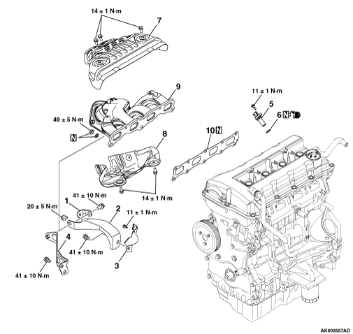


<2WD>


Removal steps

>>B<<
1.
Exhaust manifold bracket D

>>B<<
2.
Exhaust manifold bracket B


3.
Crank angle sensor cover

>>B<<
4.
Exhaust manifold bracket A

>>A<<
5.
Crank angle sensor

>>A<<
6.
O-ring


7.
Exhaust manifold upper cover


8.
Exhaust manifold lower cover


9.
Exhaust manifold


10.
Exhaust manifold gasket

<4WD>


Removal steps

>>B<<
1.
Exhaust manifold bracket C

>>B<<
2.
Exhaust manifold bracket A


3.
Crank angle sensor cover

>>A<<
4.
Crank angle sensor

>>A<<
5.
O-ring


6.
Exhaust manifold upper cover


7.
Exhaust manifold lower cover


8.
Exhaust manifold


9.
Exhaust manifold gasket

INSTALLATION SERVICE POINTS


>>A<< CRANK ANGLE SENSOR / O-RING INSTALLATION


caution
  • Do not apply a force such as torsion or twist to the O-ring during assembly of the sensor.
  • Assemble the sensor, taking care not to give a shock to it.
  • Do not use a sensor that has fallen down.
Tighten the crank angle sensor to the specified torque of 11 ± 1 N·m.

>>B<< EXHAUST MANIFOLD BRACKET A, B, C, D INSTALLATION


caution The exhaust manifold gasket, washers and nuts must not be reused.


Make sure that exhaust manifold bracket is in intimate contact with the exhaust manifold and cylinder block, and then tighten it to the specified torque.
Specified torque
    M10: 41 ± 10 N·m
    M8: 20 ± 5 N·m