Inspection Procedure 23: Alternator System


OPERATION
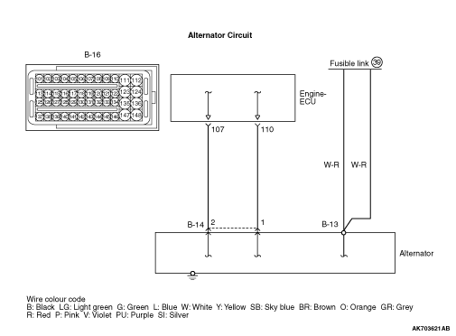
- The excitation current is supplied from the engine-ECU (terminal No. 110)
to the alternator (terminal No. 1).
- The alternator load signal is inputted from the alternator (terminal No. 2) to the
engine-ECU (terminal No. 107).
FUNCTION
- Controls the initiating excitation current to the alternator in accordance
with the signals provided by the engine-ECU.
PROBABLE CAUSES
- Failed alternator
- Open/short circuit or harness damage in alternator circuit or loose connector contact
- Failed engine-ECU
DIAGNOSIS PROCEDURE |
STEP 1. Connector check: B-13 alternator connector |
Q.
Is the check result normal?
|
 Go to Step 2 . Go to Step 2 . |
|
 Repair or replace the connector. Repair or replace the connector. |
|
STEP 2. Perform voltage measurement at B-13 alternator connector. |
|
| OK: System voltage |
Q.
Is the check result normal?
|
| Go to Step 3 . |
|
|
|
STEP 3. Check harness between battery and B-13 (terminal No. 1) alternator connector. |
|
Q.
Is the check result normal?
|
| Go to Step 4 . |
|
| Repair the damaged harness wire. |
|
STEP 4. Connector check: B-14 alternator connector |
Q.
Is the check result normal?
|
| Go to Step 5 . |
|
| Repair or replace the connector. |
|
STEP 5. Connector check: B-16 engine-ECU connector |
Q.
Is the check result normal?
|
| Go to Step 6 . |
|
| Repair or replace the connector. |
|
STEP 6. Check harness between B-14 alternator connector and B-16 (terminal No. 107) engine-ECU connector. |
|
Q.
Is the check result normal?
|
| Go to Step 7 . |
|
| Repair the damaged harness wire. |
|
STEP 7. Check harness between B-14 alternator connector and B-16 (terminal No. 110) engine-ECU connector. |
|
Q.
Is the check result normal?
|
| Go to Step 8 . |
|
| Repair the damaged harness wire. |
|
STEP 8. Replace the alternator. |
|
Q.
Does trouble symptom persist?
|
| Replace the engine-ECU. |
|
| The check is end. |
|