|
|
1.Remove the transfer from the transmission.
|
|
|
2.Remove the RR roll stopper bracket and FR roll stopper bracket from the transmission.
|
|
|
3.Remove the harness bracket from the transmission.
|
|
|
4.Remove the oil filler tube and oil level gage from the transmission.
|
|
|
5.Remove the control cable bracket and breather hose from the transmission.
|
|
|
6.Remove the corrugate clamp bracket and breather hose from the transmission.
|

|
7.Remove the torque converter from the transmission.
|
|
8.Remove the vehicle speed sensor from the transmission case.
9.Remove the O-ring from the vehicle speed sensor.
|

|
10.Remove the turbine sensor from the transmission case.
11.Remove the O-ring from the turbine sensor.
|

|
12.Remove the inhibitor switch from the transmission case.
|

|
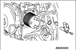
13.Remove the fluid water-cooled cooler from the transmission case.
|

|
14.Remove the O-ring from the fluid water-cooled cooler.
|

|
15.Remove the pressure test port bolt from the transmission case.
16.Remove the O-ring from the pressure test port bolt.
|

|
17.Remove the baffle plate from the converter housing.
18.Remove the O-ring from the baffle plate.
|

|
19.Remove stud bolts from the transmission case.
|

|
20.Remove the cooler tube (IN) from the side cover.
|

|
21.Remove the cooler tube (OUT) from the side cover.
|

|
22.
| caution |
Be careful not to break the terminal body.
|
Remove the snap ring from the terminal body and push the terminal body into the transmission
case.
|

|
23.Remove the control valve cover from the transmission case.
|

|
24.Remove the control valve cover gasket from the transmission case.
|

|
25.
| caution |
- Mounting bolt A is a hexagon head bolt.
- Mounting bolt B is a hexagon socket head bolt.
|
Remove control valve assembly mounting bolts A and B.
|
|
Bolt code
|
A
|
B
|
Shank length mm
|
71.5
|
58
|
No. of bolts
|
5
|
4
|
|
|

|
26.
| caution |
Remove the control valve assembly by pulling it straight.
|
Remove the control valve assembly from the transmission case.
|

|
27.
| caution |
Be careful not to drop the manual valve.
|
Remove the manual valve from the control valve.
|

|
28.Remove the oil temperature sensor and bracket from the control valve.
29.Remove the bracket from the oil temperature sensor.
|

|
30.Remove the terminal assembly from the control valve.
|

|
31.Remove the detent spring.
|

|
32.Remove lip seals from the transmission case.
|

|
33.Remove the ATF adjusting bolt from the transmission case.
34.Remove the O-ring from the ATF adjusting bolt.
|

|
35.
| caution |
Mounting bolts are Torx E20 bolts.
|
Remove converter housing mounting bolts.
|

|
36.Lightly tap the converter housing with a plastic hammer or equivalent to remove.
|

|
37.Using the Special Tools, remove the outer race of the reduction gear bearing from the
converter housing.
- Slide hammer puller (MB992039)
- Slide hammer (MB990590)
|

|
38.Remove the reduction gear taper bearing shim from the converter housing.
|

|
39.Using the Special Tools, remove the outer race of the differential side bearing from the
converter housing.
- Slide hammer puller (MB992039)
- Slide hammer (MB990590)
|

|
40.Remove the differential taper bearing shim from the converter housing.
|

|
41.Remove the O-ring from the input shaft.
|

|
42.Remove the oil pump assembly and oil strainer from the transmission case.
|

|
43.Remove the oil strainer from the oil pump assembly.
|
|
Bolt code
|
A
|
B
|
No. of bolts
|
2
|
1
|
|
|

|
44.Remove the magnet from the oil strainer.
|

|
45.Remove the O-ring from the transmission case.
|

|
46.Remove the input shaft.
|
|
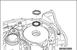
47.Remove the bearing race and needle bearing from the 3-5 reverse clutch drum.
|

|
48.Remove the 3-5 reverse clutch assembly.
|

|
49.Remove the needle bearing from the FR sun gear.
|

|
50.Remove the FR sun gear.
|

|
51.Remove the needle bearing from the FR sun gear.
|

|
52.Remove the FR internal gear and FR carrier as one unit.
|

|
53.Remove the FR internal gear and needle bearing from the FR carrier.
|

|
54.Remove the low clutch assembly.
|

|
55.Remove the thrust washer from the drum support.
|
|
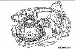
56.Remove the differential assembly from the transmission case.
|

|
57.Remove the parking plate.
|

|
58.Remove the return spring.
|

|
59.Remove the parking shaft.
|

|
60.Remove the parking pawl.
|

|
61.Remove the reduction gear lubrication tube.
|

|
62.Remove the reduction gear assembly .
|

|
63.
| caution |
Mounting bolts are Torts E16 bolts.
|
Remove the side cover.
|

|
64.Remove the spacer and needle bearing from the side cover.
|

|
65.Remove the O-ring from the transmission case.
|

|
66.Remove the high clutch assembly.
|

|
67.Remove the reduction sun gear.
|

|
68.Remove the reduction carrier.
|

|
69.Remove the needle bearing from the reduction internal gear.
|

|
70.Remove the reduction internal gear from the high clutch hub.
|

|
71.Remove the needle bearing from the reduction internal gear.
|

|
72.Remove the high clutch hub.
|

|
73.Remove the needle bearing from the RR sun gear on the rear side.
|

|
74.Remove the RR sun gear on the rear side.
|

|
75.Remove the needle bearing from the RR carrier assembly.
|

|
76.
| caution |
Check the plates for damage, deformation, surface burn or permanent strain.
If faulty, replace.
|
Remove the 2-6 brake retaining plate, drive plate and driven plate from the transmission
case.
|

|
77.Using a flat-head screwdriver or equivalent, remove the snap ring.
|

|
78.Remove the one-way clutch and RR carrier assembly as one unit.
|

|
79.Separate the one-way clutch and RR carrier assembly.
|

|
80.Remove the needle bearing from the RR carrier assembly.
|

|
81.Using a flat-head screwdriver or equivalent, remove the snap ring.
|

|
82.
| caution |
Check the plates for damage, deformation, surface burn or permanent strain.
If faulty, replace.
|
Remove the low-reverse brake retaining plate, drive plate and driven plate.
|

|
83.Remove the RR sun gear on the front side.
|

|
84.Remove the bearing race from the RR sun gear on the front side.
|

|
85.Remove the needle bearing.
|

|
86.Using the special tool, spring compressor (MB992195), remove the snap ring.
|

|
87.Remove the diaphragm spring retainer.
|

|
88.Remove the diaphragm spring.
|

|
89.
| caution |
Do not feed air abruptly. Otherwise, the low-reverse brake piston may
become stuck in the clutch drum.
|
Feed air through the oil hole as indicated in the illustration to remove the low-reverse
brake piston from the transmission case.
|

|
90.Remove D-rings from the low-reverse brake piston.
|

|
91.
| caution |
Mounting bolts are Torx E18 bolts.
|
Remove the output gear set.
|

|
92.Remove the O-ring from the transmission case.
|

|
93.
| caution |
Do not damage the transmission case when removing the side oil seal.
|
Using a flat-head screwdriver or equivalent, remove the side oil seal from the transmission
case.
|

|
94.Using the Special Tools, remove the outer race of the reduction gear bearing from the
transmission case equivalent.
- Slide hammer puller (MB992039)
- Slide hammer (MB990590)
|

|
95.Using the Special Tools, remove the outer race of the differential side bearing from the
transmission case.
- Slide hammer puller (MB992039)
- Slide hammer (MB990590)
|

|
1.
| caution |
Never reuse the outer race.
|
Using the special tool, Bearing outer race installer (MB991550), Install the outer race
of the differential side bearing on the transmission case.
|

|
2.
| caution |
Never reuse the outer race.
|
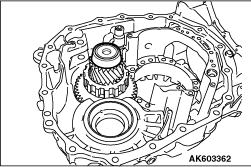
Using the special tools, install the outer race of the reduction gear bearing on the transmission
case.
- Installer cap (MD998812)
- Installer-100 (MD998813)
- Installer adapter (MD998830)
|




|
3.
| caution |
- Apply ATF to the bearing so that the interference can be
adjusted in a smooth condition.
- Measure the end play at more than two locations and obtain the average of the measurements.
|
Measure an interference (A) of the reduction gear assembly in the following procedure.
Refer to "SERVICE DATA" for the interference of the reduction gear assembly.
(1)
Install the reduction gear assembly on the transmission case.
(2)
Set the outer race on the reduction gear bearing.
(3)
Measure distance L1 from the outer race to the end face of the transmission case.
(4)
Place a block on the end face of the converter housing and measure distance L2 to the
reduction gear taper bearing shim mounting surface.
(5)
Calculate distance L3 from the end face of the converter housing to the outer race
of the reduction gear assembly from the following formula.
L3 = L2 - Height of block
(6)
Calculate the thickness of the reduction gear taper bearing shim from the following
formula.
Thickness of reduction gear taper bearing shim = L3 - L1 + Interference
|
|
4.
| caution |
Never reuse the reduction gear taper bearing shim.
|
Install a selected reduction gear taper bearing shim on the converter housing. Refer to
"SERVICE DATA" for selecting the reduction gear taper bearing shim.
|

|
5.
| caution |
Never reuse the outer race.
|
Using the special tools, install the outer race of the reduction gear bearing on the converter
housing.
- Installer cap (MD998812)
- Installer-100 (MD998813)
- Installer adapter (MD998830)
|


|
6.
| caution |
- Apply ATF to the bearing so that the interference can be
adjusted in a smooth condition.
- Measure the end play at more than two locations and obtain the average of the measurements.
|
Measure an interference (A) of the differential assembly in the following procedure. Refer
to "SERVICE DATA" for the interference of the differential assembly.
(1)
Install the differential assembly on the transmission case.
(2)
Set the outer race on the differential side bearing.
(3)
Measure distance L1 from the outer race to the end face of the transmission case.
(4)
Measure distance L2 from the end face of the converter housing to the differential taper
bearing shim mounting surface of the converter housing.
(5)
Calculate the thickness of the differential taper bearing shim from the following
formula.
Thickness of differential taper bearing shim = L2 - L1 + Interference
|
|
7.
| caution |
Never reuse the differential taper bearing shim.
|
Install a selected differential taper bearing shim on the converter housing. Refer to
"SERVICE DATA" for selecting the differential taper bearing shim.
|

|
8.
| caution |
Never reuse the outer race.
|
Using the special tool, Bearing outer race installer (MB991445), install the outer race
of the differential taper bearing on the converter housing.
|
|
9.
| caution |
- Never reuse the O-rings.
- Apply ATF to the O-rings before installation.
|
Install an O-ring on the transmission case.
|
|
10.
| caution |
Mounting bolts are Torx E18 bolts.
|
Install the Output gear set. Refer to the following or the exploded view for the tightening
torque.
Tightening torque: 41 N·m
|
|
11.
| caution |
- Never reuse the D-rings.
- Apply ATF to the D-rings before installation.
|
Install D-rings on the low-reverse brake piston.
|

|
12.
| caution |
Apply ATF to the low-reverse brake piston before installation.
|
Install the low-reverse brake piston on the transmission case.
|
|
13.Install the diaphragm spring.
|
|
14.Install the diaphragm spring retainer.
|
|
15.Using the special tool, Spring compressor (MB992195), install the snap ring.
|


|
16.
| caution |
Measure the end play at more than two locations and obtain the average
of the measurements.
|
Measure the clearance (A) of the low-reverse brake using the following procedure. Refer
to "SERVICE DATA" for the specified low-reverse brake clearance.
(1)
While compressing the drive plates, driven plates and retaining plate, measure the thickness
L1 of the pack.
|
|
| note |
If there is no appropriate plate, use the special tool,MD998917.
|
|
|
|
Compression load (N)
|
7056 - 8056
|
|
(2)
Measure thickness L2 of the one-way clutch.
(3)
Measure distance L3 from the end face of the transmission case to the low-reverse brake
piston.
(4)
Temporarily assemble the snap ring, one-way clutch and snap ring to the transmission case.
(5)
Measure distance L4 from the end face of the transmission case to the one-way clutch,
while pulling up the one-way clutch.
(6)
Remove the temporarily assembled snap ring, one-way clutch and snap ring from the
transmission case.
(7)
Calculate the clearance using the following formula.Clearance = L3 - (L1 + L2 + L4)
(8)
Select an appropriate retaining plate so that the specified clearance is obtained.
Refer to "SERVICE DATA" for selecting the retaining plate.
|
|
17.
| caution |
- Apply Vaseline to the needle bearing before installation.
- Ensure that the needle bearing faces the correct direction.
|
Install the needle bearing.
|
|
18.
| caution |
Apply Vaseline to the bearing race before installation.
|
Install the bearing race on the RR sun gear on the front side.
|
|
19.Install the RR sun gear on the front side.
|
|
20.
| caution |
- Apply Vaseline to the needle bearing before installation.
- Ensure that the needle bearing faces the correct direction.
|
Install the needle bearing on the RR carrier assembly.
|

|
21.Install the RR carrier assembly.
|

|
22.
| caution |
Ensure that the various plates are installed in the correct order.
|
Install the low-reverse brake drive plate, driven plate and selected retaining plate on
the transmission case.
|
|
23.Using a flat-head screwdriver or equivalent, install the snap ring.
|

|
24.Install the one-way clutch.
|
|
25.Using a flat-head screwdriver or equivalent, install the snap ring.
|


|
26.
| caution |
Measure the end play at more than two locations and obtain the average
of the measurements.
|
Measure the clearance (A) of the 2-6 brake using the following procedure. Refer to "SERVICE
DATA" for the specified 2-6 brake clearance.
(1)
While compressing the drive plates, driven plates and retaining plate, measure thickness
L1 of the pack.
|
|
| note |
If there is no appropriate plate, use the special tool,MD998917.
|
|
(2)
Measure distance L2 from the end face of the transmission case to the snap ring.
(3)
|
|
| caution |
When measuring L3, use the same straight bar as used when L2 is measured.
|
|
Measure distance L3 from the end face of the side cover to the 2-6 brake piston.
(4)
Calculate the clearance using the following formula.
Clearance = L2 - (L1 + L3)
(5)
Select an appropriate retaining plate so that the specified clearance is obtained.
Refer to "SERVICE DATA" for selecting the retaining plate.
|
|
27.
| caution |
- Apply Vaseline to the needle bearing before installation.
- Ensure that the needle bearing faces the correct direction.
|
Install the needle bearing on the RR carrier assembly.
|
|
28.Install the RR sun gear on the rear side.
|
|
29.
| caution |
- Apply Vaseline to the needle bearing before installation.
- Ensure that the needle bearing faces the correct direction.
|
Install the needle bearing on the RR sun gear on the rear side.
|
|
30.Install the high clutch hub.
|
|
31.
| caution |
- Apply Vaseline to the needle bearing before installation.
- Ensure that the needle bearing faces the correct direction.
|
Install the needle bearing on the reduction internal gear.
|
|
32.Install the reduction internal gear on the high clutch hub.
|
|
33.
| caution |
- Apply Vaseline to the needle bearing before installation.
- Ensure that the needle bearing faces the correct direction.
|
Install the needle bearing on the reduction internal gear.
|
|
34.Install the reduction carrier.
|
|
35.Install the reduction sun gear.
|


|
36.
| caution |
Measure the end play at more than two locations and obtain the average
of the measurements.
|
Measure the reduction sun gear end play (A) using the following procedure. Refer to "SERVICE
DATA" for the specified reduction sun gear end play (A).
(1)
Measure distance L1 from the reduction carrier to the end face of the transmission case.
(2)
Measure distance L2 from the reduction carrier to the reduction sun gear.
(3)
Measure distance L3 from the end face of the side cover to the end face of the high clutch
support area.
(4)
Calculate the end play using the following formula.
End play = L3 - (L1 - L2) - Thickness of straight bar - Thickness of spacer
(5)
Select an appropriate spacer so that the specified end play is obtained. Refer to
"SERVICE DATA" for selecting the spacer.
|


|
37.
| caution |
Measure the end play at more than two locations and obtain the average
of the measurements.
|
Measure the side cover end play (A) in the following procedure. Refer to "SERVICE DATA"
for the specified side cover end play (A).
(1)
Measure distance L1 from the reduction carrier to the end face of the transmission case.
(2)
Measure distance L2 from the end face of the side cover to the needle bearing mounting
surface.
(3)
Measure distance L3 from the contact surface with the needle bearing of the high clutch
drum to the snap ring of the cancel cover in the following procedure.
.....1.
Measure distance L4 from the high clutch drum edge to the snap ring of the cancel cover.
.....2.
Measure height L5 of the high clutch drum.
.....3.
Measure distance L6 from the underside of the high clutch drum to the contact surface
with the needle bearing.
.....4.
Calculate L3 using the following formula.
L3 = L5 - (L4 + L6) -Thickness of straight bar
(4)
Calculate the end play using the following formula.
End play = L3 - (L1 - L2) - Thickness of straight bar - Thickness
of spacer
(5)
Select an appropriate needle bearing so that the specified end play is obtained. Refer
to "SERVICE DATA" for selecting the needle bearing.
|
|
38.Install the high clutch assembly.
|

|
39.
| caution |
Ensure that the various plates are installed in the correct order.
|
Install the 2-6 brake drive plate, driven plate and selected retaining plate on the transmission
case.
|
|
40.
| caution |
- Never reuse the O-rings.
- Apply ATF to the O-rings before installation.
|
Install an O-ring on the transmission case.
|
|
41.
| caution |
- Never reuse the spacer.
- Apply Vaseline to the spacer and needle bearing before installation.
- Ensure that the needle bearing faces the correct direction.
|
Install an appropriate spacer and the needle bearing on the side cover.
|

|
42.
| caution |
- Before applying the sealant, thoroughly clean the mounting
surface so that it is completely free of moisture, lubricant and the old sealant.
- The start and finish of the bead should be close to the middle of any pair of the
adjoining bolt holes.
|
Apply Three Bond 1216B to the transmission case mounting surface of the side cover (almost
the centre line of the surface).
|
|
43.
| caution |
Mounting bolts are Torx E16 bolts.
|
Install the side cover on the transmission case. Refer to the following or the exploded
view for the tightening torque.
Tightening torque: 27 N·m
|


|
44.
| caution |
Measure the end play at more than two locations and obtain the average
of the measurements.
|
Measure the drum support end play (A) using the following procedure. Refer to "SERVICE
DATA" for the specified drum support end play (A).
(1)
Measure distance L1 between the end face of the RR internal gear splines and the oil pump
mounting surface of the transmission case.
(2)
Measure distance L2 between the thrust washer mounting surface of the drum support and
the oil pump mounting surface of the transmission case.
(3)
Measure distance L3 using the following procedure.
.....1.
Install the FR carrier on the low clutch assembly.
.....2.
|
|
| caution |
- Apply Vaseline to the needle bearing before installation.
- Ensure that the needle bearing faces the correct direction.
|
|
Install the needle bearing on the FR carrier.
.....3.
Install the FR internal gear on the FR carrier.
.....4.
|
|
| caution |
- Apply Vaseline to the needle bearing before installation.
- Ensure that the needle bearing faces the correct direction.
|
|
Install the needle bearing on the FR sun gear.
.....5.
Install the FR sun gear.
.....6.
|
|
| caution |
- Apply Vaseline to the needle bearing before installation.
- Ensure that the needle bearing faces the correct direction.
|
|
Install the needle bearing on the FR sun gear.
.....7.
Install the 3-5 reverse clutch assembly.
.....8.
Measure distance L3 between A and B.
(4)
Calculate the end play using the following formula.
End play = L3 - (L1 - L2) - Thrust washer thickness
(5)
Select an appropriate thrust washer so that the specified end play is obtained. Refer
to "SERVICE DATA" for selecting the thrust washer.
|
|
45.Install the reduction gear assembly.
|
|
46.Install the reduction gear lubrication tube.
|
|
47.Install the parking pawl.
|
|
48.Install the parking shaft.
|
|
49.Install the return spring.
|
|
50.Install the parking plate on the transmission case. Refer to the following or the exploded
view for the tightening torque.
Tightening torque: 7.9 N·m
|
|
51.Install the differential gear assembly.
|
|
52.
| caution |
- Ensure that the claws on the thrust washer are correctly
engaged with the holes in the drum support.
- Apply Vaseline to the thrust washer before installation.
|
Install an appropriate thrust washer on the drum support.
|
|
53.Install the low clutch assembly.
|

|
54.Install the FR carrier on the low clutch assembly.
|

|
55.
| caution |
- Apply Vaseline to the needle bearing before installation.
- Ensure that the needle bearing faces the correct direction.
|
Install the needle bearing on the FR carrier.
|

|
56.Install the FR internal gear on the FR carrier.
|
|
57.
| caution |
- Apply Vaseline to the needle bearing before installation.
- Ensure that the needle bearing faces the correct direction.
|
Install the needle bearing on the FR sun gear.
|
|
58.Install the FR sun gear.
|
|
59.
| caution |
- Apply Vaseline to the needle bearing before installation.
- Ensure that the needle bearing faces the correct direction.
|
Install the needle bearing on the FR sun gear.
|
|
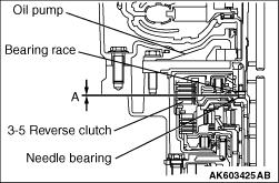
60.Install the 3-5 reverse clutch assembly.
|


|
61.
| caution |
Measure the end play at more than two locations and obtain the average
of the measurements.
|
Measure the 3-5 reverse clutch end play (A) using the following procedure. Refer to "SERVICE
DATA" for the specified 3-5 reverse clutch end play (A).
(1)
Measure distance L1 between the oil pump assembly end face and A.
(2)
Measure distance L2 between A and the bearing race mounting surface.
(3)
Measure distance L3 between the oil pump mounting surface of the transmission case and
the needle bearing mounting surface of the 3-5 reverse clutch drum.
(4)
Measure thickness L4 of the needle bearing.
(5)
Calculate the end play using the following formula.
End play = L3 - (L1 - L2) - L4 - Bearing race thickness
(6)
Select an appropriate bearing race so that the specified end play is obtained. Refer
to "SERVICE DATA" for selecting the bearing race.
|

|
62.
| caution |
- Apply Vaseline to the needle bearing before installation.
- Ensure that the needle bearing faces the correct direction.
|
Install the needle bearing on the 3-5 reverse clutch drum.
|
|
63.Install the input shaft.
|
|
64.
| caution |
- Never reuse the O-rings.
- Apply ATF to the O-rings before installation.
|
Install an O-ring on the transmission case.
|
|
65.Install the magnets on the oil strainer.
|
|
66.
| caution |
- Never reuse the oil strainer.
- Apply ATF to the O-ring of the oil strainer.
|
Install the oil strainer on the oil pump assembly. Refer to the following or the exploded
view for the tightening torque.
|
|
Bolt code
|
A
|
B
|
No. of bolts
|
2
|
1
|
|
Tightening torque: 9.4 N·m
|

|
67.
| caution |
Apply Vaseline to the bearing race before installation.
|
Install an appropriate bearing race on the oil pump assembly.
|

|
68.
| caution |
- Never reuse the O-rings.
- Apply ATF to the O-rings before installation.
- Apply the ATF as little as possible because too much ATF applied to the O-ring,
could cause some confusion over oil leakage.
|
Install an O-ring on the oil pump.
|
|
69.Install the oil pump assembly and oil strainer as one unit. Refer to the following or
the exploded view for the tightening torque.
Tightening torque: 21 N·m
|
|
70.
| caution |
- Never reuse the O-rings.
- Apply ATF to the O-rings before installation.
|
Install an O-ring on the input shaft.
|

|
71.
| caution |
- Before applying the sealant, thoroughly clean the mounting
surface so that it is completely free of moisture, lubricant and the old sealant.
- The start and finish of the bead should be close to the middle of any pair of the
adjoining bolt holes.
- Apply a double bead of sealant in sections A.
|
Apply Three Bond 1216B to the transmission case mounting surface of the converter housing
(almost the centre line of the surface).
|
|
L1 mm
|
3 - 5
|
L2 mm
|
2.3
|
L3 mm
|
1.8
|
|
|
|
72.
| caution |
Mounting bolts are Torx E20 bolts.
|
Install the converter housing on the transmission case. Refer to the following or the
exploded view for tightening torque.
Tightening torque: 47 N·m
|


|
73.
| caution |
- Never reuse the side oil seal.
- Apply ATF to the side oil seal before installation.
|
Using the Special Tools, install a side oil seal.
- Oil seal installer (MB992197)
- Handle (MB992075)
| caution |
- Ensure that the side oil seal is installed to the specified depth shown in the table below.
- Measure the installed depth of the seal at four locations diagonally. Any difference between the measurements should be no more than 0.3 mm.
|
|
Depth of insertion (A)
|
4.0 ± 0.5 mm
|
|
|
|
|
74.
| caution |
- Never reuse the O-rings.
- Apply ATF to the O-rings before installation.
|
Install an O-ring on the ATF adjusting bolt.
75.Install the ATF adjusting bolt on the transmission case. Refer to the following or
the exploded view for the tightening torque.
Tightening torque: 7.4 N·m
|
|
76.
| caution |
- Never reuse the lip seals.
- Apply ATF to the lip seals before installation.
|
Install the lip seals on the transmission case.
|
|
77.Install the detent spring on the transmission case. Refer to the following or the exploded
view for the tightening torque.
Tightening torque: 4.9 N·m
|
|
78.Install the bracket on the oil temperature sensor.
79.Install the oil temperature sensor on the control valve. Refer to the following or
the table below view for the tightening torque.
Tightening torque: 7.9 N·m
|

|
80.
| caution |
Check the oil pressure switch connectors (each indicated with an arrow)
for correct fit.
|
Install the terminal assembly on the control valve.
|
|
81.
| caution |
Apply ATF to the manual valve before installation.
|
Install the manual valve on the control valve.
|

|
82.Press the terminal body into the transmission case.
|

|
83.
| caution |
Ensure that the notch in the manual valve is engaged with the lug on the manual plate.
|
Install the control valve assembly on the transmission case.
|
|
84.
| caution |
- Mounting bolt A is a hexagon head bolt.
- Mounting bolt B is a hexagon socket head bolt.
|
Install the control valve assembly mounting bolts A and B. Refer to the following or the
exploded view for the tightening torque.
|
|
Bolt code
|
A
|
B
|
Shank length mm
|
71.5
|
58
|
No. of bolts
|
5
|
4
|
|
Tightening torque: 9.0 N·m
|
|
85.
| caution |
- Never reuse the control valve cover gasket.
- Thoroughly clean the control valve cover gasket mounting surface of the case so
that it is completely free of moisture, lubricant and the old gasket.
|
Install the control valve cover gasket on the transmission case.
|
|
86.Install the control valve cover on the transmission case. Refer to the following or the
exploded view for the tightening torque.
Tightening torque: 9.0 N·m
|
|
87.
| caution |
Never reuse the snap ring.
|
Install a snap ring on the terminal body.
|
|
88.
| caution |
Never reuse the copper washers.
|
Install the cooler tube (OUT) onto the side cover. Refer to the following or the exploded
view for the tightening torque.
Tightening torque
- Eye bolt: 39.2 N·m
- Cooler tube: 21.6 N·m
|

|
89.
| caution |
Never reuse the copper washers.
|
Install the cooler tube (IN) on the side cover. Refer to the following or the exploded
view for the tightening torque.
Tightening torque: 39.2 N·m
| caution |
Ensure that the cooler tube (IN) is against the stop on the side cover.
|
|

|
90.
| caution |
Ensure that the stud bolts protrude from the case as much as indicated
in the table below.
|
|
Stud bolt code
|
1
|
2
|
Projection amount mm
|
39.9
|
61.4
|
|
|
Install stud bolt 1 and 2 on the transmission case.
|
|
91.
| caution |
- Never reuse the O-rings.
- Apply ATF to the O-rings before installation.
|
Install an O-ring on the baffle plate.
92.Install the baffle plate on the converter housing. Refer to the following or the exploded
view for the tightening torque.
Tightening torque: 6.6 N·m
|
|
93.
| caution |
- Never reuse the O-rings.
- Apply ATF to the O-rings before installation.
|
Install an O-ring on the pressure test port bolt.
94.Install the pressure test port bolt on the transmission case. Refer to the following
or the exploded view for the tightening torque.
Tightening torque: 7.4 N·m
|
|
95.
| caution |
- Never reuse the O-rings.
- Apply ATF to the O-rings before installation.
|
Install an O-ring on the water-cooled fluid cooler.
|
|
96.Install the water-cooled fluid cooler on the transmission case. Refer to the following
or the exploded view for the tightening torque.
Tightening torque: 4.3 N·m
|


|
97.Install an inhibitor switch using the following procedure.
(1)
|
|
| caution |
- Never reuse the inhibitor switch.
- When loosely installing the switch, insert it squarely onto the manual shaft. (Do
not hold the switch at an angle.)
|
|
Loosely install an inhibitor switch on the manual shaft.
(2)
Install the shift plate on the manual lever.
(3)
Install the spring washer and jam nut on the manual shaft. Refer to the following
or the exploded view for the tightening torque.
Tightening torque: 22 ± 3 N·m
(4)
Set the manual shaft to Range N.
(5)
Align the hole in the inhibitor position switch with the hole in the manual control lever.
With the holes aligned, insert a pin (Φ5 mm) or equivalent through the holes. Now, tighten
the bolt to the specified torque shown in the table below or in the exploded view. Refer to
the following or the exploded view for the tightening torque.
Tightening torque: 5.9 N·m
|
|
98.
| caution |
- Never reuse the O-rings.
- Apply ATF to the O-rings before installation.
|
Install an O-ring on the turbine sensor.
99.Install the turbine sensor on the transmission case. Refer to the following or the
exploded view for the tightening torque.
Tightening torque: 5.9 N·m
|
|
100.
| caution |
- Never reuse the O-rings.
- Apply ATF to the O-rings before installation.
|
Install an O-ring on the vehicle speed sensor.
101.Install the vehicle speed sensor on the transmission case. Refer to the following
or the exploded view for the tightening torque.
Tightening torque: 5.9 N·m
|

|
102.
| caution |
Measure the end play at more than two locations and obtain the average
of the measurements.
|
Install the torque converter on the transmission. Ensure that the dimension A is to the
specification.
103.Install the control cable bracket and breather hose on the transmission. Refer to
the following or the exploded view for the tightening torque.
Tightening torque: 23 ± 3 N·m
104.Install the oil filler tube and oil level gage on the transmission. Refer to the following
or the exploded view for the tightening torque.
Tightening torque: 11 ± 1 N·m
105.Install the harness bracket on the transmission. Refer to the following or the exploded
view for the tightening torque.
Tightening torque: 23 ± 3 N·m
106.Install the corrugate clamp bracket on the transmission. Refer to the following or
the exploded view for the tightening torque.
Tightening torque: 23 ± 3 N·m
107.Install the RR roll stopper bracket and FR roll stopper bracket on the transmission.
Refer to the following or the exploded view for the tightening torque.
Tightening torque: 90 ± 10 N·m
108.Install the transfer on the transmission. Refer to the following or the exploded view
for the tightening torque.
Tightening torque: 68 ± 9 N·m
|


