DISC BRAKE PAD CHECK AND REPLACEMENT
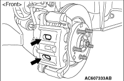 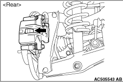 |
1.Visually check the thickness of brake pad from the inspection hole of the caliper body. Standard value: 10.0 mm Limit: 2.0 mm 2.When the thickness is lower than the limit value, replace both brake pads (right and left) as a set. |
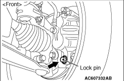 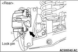 |
3.Remove the parts indicated in the figure, swivel the caliper assembly upward and retain it with a wire or similar tool. |
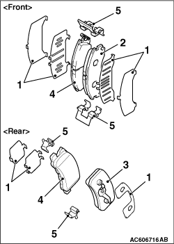 |
4.Remove the following parts from the caliper assembly. (1) Shim (2) Pad assembly <front> (3) Pad & clip assembly <rear> (4) Pad assembly <RH>, pad & wear indicator assembly <LH> (5) Clip 5.In order to measure the brake drag force after pad installation, measure the hub sliding torque with no pad attached (Refer to  ). ).6.Install the pad and caliper assembly, and check the brake drag force (Refer to ).
|