|
|
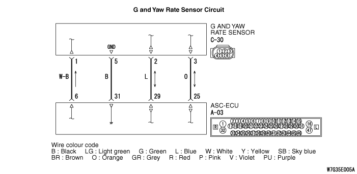
The G and yaw rate sensor outputs the signal to ASC-ECU via the special CAN bus lines.
|
|
|
This diagnosis code is set when ASC-ECU cannot receive the signal sent from the G and yaw rate sensor.
|
|
|
- Wiring harness or connector failure for the special CAN bus lines between ASC-ECU and the G and yaw rate sensor
- G and yaw rate sensor malfunction
- ASC-ECU malfunction
|
|
|
Use M.U.T.-III to diagnose the CAN bus lines.
|
|
|
Q.
Is the check result normal?
|
|
|
 Repair the CAN bus lines (Refer to GROUP 54C - CAN Bus Diagnosis table Repair the CAN bus lines (Refer to GROUP 54C - CAN Bus Diagnosis table  ). On completion, go to Step 2. ). On completion, go to Step 2.
|
|
|
|
|
|
Q.
Is the diagnosis code No.U0125 set?
|
|
|
This diagnosis is complete.
|
|
|
|
|
|
Q.
Is the check result normal?
|
|
|
Repair the connector, and then go to Step 5.
|
|
|
|
|
|
- Check for open circuit in communication circuit
|
|
|
Q.
Is the check result normal?
|
|
|
Repair the wiring harness, and then go to Step 5.
|
|
|
|
|
|
Q.
Is the diagnosis code No.U0125 set?
|
|
|
 Replace the G and yaw rate sensor (Refer to ), and then go to Step 6. Replace the G and yaw rate sensor (Refer to ), and then go to Step 6.
|
|
|
|
|
|
This diagnosis is complete.
|
|
|
|
|
|
Q.
Is the diagnosis code No.U0125 set?
|
|
|
Replace the ASC-ECU (Refer to ), and then go to Step 7.
|
|
|
|
|
|
This diagnosis is complete.
|
|
|
|
|
|
Q.
Is the diagnosis code No.U0125 set?
|
|
|
This diagnosis is complete.
|
|
|
|