Code No.B2412 LF antenna power voltage
| caution |
|


DIAGNOSTIC FUNCTION
JUDGMENT CRITERIA
PROBABLE CAUSES
- Damaged wiring harness and connectors
- Malfunction of the KOS-ECU
DIAGNOSTIC PROCEDURE
STEP 1. M.U.T.-III CAN bus diagnostics
Q.
Is the check result normal?


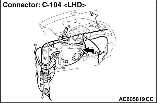
STEP 2. Connector check: C-104 KOS-ECU connector
Q.
Is the check result normal?
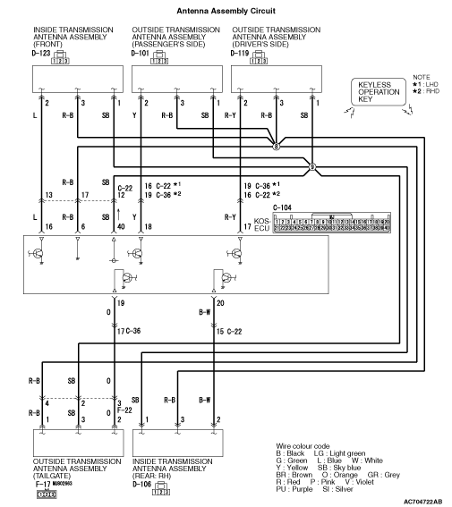
STEP 3. Check the wiring harness between KOS-ECU and each inside and outside antenna.
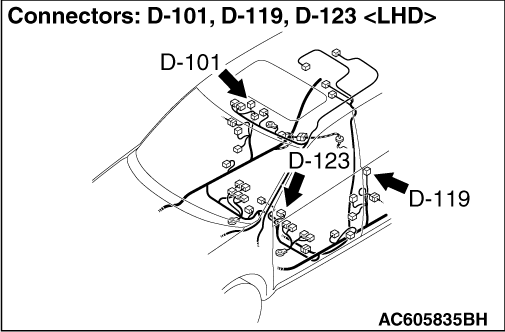
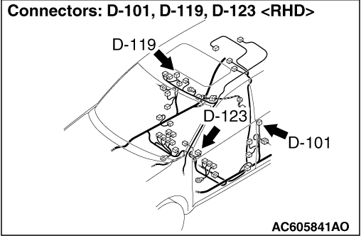
- Wiring harness between C-104 KOS-ECU connector terminal No. 40 and D-119 outside transmitter antenna assembly (driver’s side) connector terminal No. 1
- Wiring harness between C-104 KOS-ECU connector terminal No. 40 and D-101 outside transmitter antenna assembly (front passenger’s side) connector terminal No. 1
- Wiring harness between C-104 KOS-ECU connector terminal No. 40 and D-123 inside transmitter antenna (front) connector terminal No. 1
- Wiring harness between C-104 KOS-ECU connector terminal No. 40 and D-106 inside transmitter antenna (rear: RH) connector terminal No. 1
- Wiring harness between C-104 KOS-ECU connector terminal No. 40 and F-17 outside transmitter antenna assembly (tailgate) connector terminal No. 3
| note | Before the wiring harness inspection, inspect C-22 and F-22 <the outside transmitter antenna (tailgate)> intermediate connectors, and repair them if necessary. |
Q.
Is the check result normal?
STEP 4. Check whether the diagnosis code is reset.
| (1)Erase the diagnosis code. |
| (2)Turn the ignition switch from the LOCK (OFF) position to the ON position. |
| (3)Check if the diagnosis code is set. |
Q.
Is the diagnosis code set?