|
|
Q.
Is the check result normal?
|
|
|
 Repair the connector, and then go to Step 9. Repair the connector, and then go to Step 9.
|
|
|
|
|
|
Check the Fuel pump and gauge unit (main) and fuel gauge unit (sub) <4WD only>. Refer to  . .
|
|
|
Q.
Is the check result normal?
|
|
|
Replace the Fuel pump and gauge unit (main) and fuel gauge unit (sub) <4WD only>.
|
|
|
|
|
|
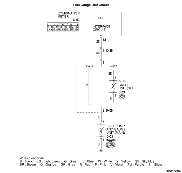
(1)Disconnect the D-22 fuel pump and fuel gauge unit (main) connector.
|
|
|
(2)Use the special tool Check harness (MB991219) to connect a test lamp (12 V - 3.4 W) between the wiring harness connector terminals 1 and 2.
|
|
|
(3)Turn the ignition switch to the ON position.
|
|
|
(4)Check if the test lamp illuminates.
OK: Illuminates
|
|
|
Q.
Is the check result normal?
|
|
|
(1)Disconnect the fuel pump and gauge unit (main) connector, the measure at the harness side.
|
|
|
(2)Measure the resistance between the D-22 fuel pump and gauge unit (main) connector terminal No. 1 and the body earth.
OK: Continuity exists (2 Ω or less)
|
|
|
Q.
Is the check result normal?
|
|
|
Q.
Is the check result normal?
|
|
|
Repair the wiring harness, and then go to Step 9.
|
|
|
|
|
|
Q.
Is the check result normal?
|
|
|
Repair the connector, and then go to Step 9.
|
|
|
|
|
|
Q.
Is the check result normal?
|
|
|
Repair the wiring harness, and then go to Step 9.
|
|
|
|
|
|
- Item 03: Fuel gauge (target value): 0 →100%
|
|
|
OK: The fuel gauge operates.
|
|
|
Q.
Is the check result normal?
|
|
|
Replace the combination meter
|
|
|
|
|
|
Check again if the diagnosis code is set to the combination meter.
|
|
|
(1)Erase the diagnosis code.
|
|
|
(2)Turn the ignition switch from "LOCK" (OFF) position to "ON" position.
|
|
|
(3)Check if diagnosis code is set.
|
|
|
Q.
Is the diagnosis code set?
|
|
|
 Replace the combination meter Replace the combination meter
|
|
|
|
|
|
The diagnosis is complete.
|
|
|
|