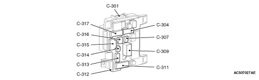
Terminal No.
|
Check item
|
Check condition
|
Normal condition
|
1, 2
|
-
|
-
|
-
|
3
|
Photo sensor power supply
|
Ignition switch: ON
|
5 V
|
4-9
|
-
|
-
|
-
|
10
|
Input to front passenger’s door lock actuator (unlock)
|
Front passenger’s door lock: Unlocked
|
0 V
|
11
|
Input to driver’s door lock actuator (lock)
|
Driver’s door lock: Locked
|
0 V
|
12
|
Defogger output
|
Defogger switch: ON
|
0 V
|
13-17
|
-
|
-
|
-
|
18
|
Earth (photo sensor)
|
Always
|
0 V
|
19
|
Hazard switch input
|
Hazard switch: ON
|
0 V
|
20
|
Photo sensor input
|
Ignition switch: ON, Sensor illumination: Dark to Bright
|
0 to approximately 4 V
|
21
|
Windshield wiper backup input
|
Windshield low-speed wiper switch or windshield high-speed wiper switch: ON
|
0 V
|
22
|
Input to driver’s door lock actuator (unlock)
|
Driver’s door lock: Unlocked
|
0 V
|
23
|
-
|
-
|
-
|
24
|
Input to remote controlled mirror switch (folding/unfolding switch)
|
Remote controlled mirror switch (folding/unfolding switch): ON
|
0 V
|
Terminal No.
|
Check item
|
Check condition
|
Normal condition
|
1
|
Stop lamp switch power supply
|
Stop lamp switch: ON
|
System voltage
|
2
|
Inhibitor switch (R) input
|
Selector lever: R
Ignition switch: ON
|
System voltage
|
3
|
Position lamp (LH) output
|
With position lamp ON
|
System voltage
|
4
|
Front wiper motor (HI) power supply
|
When windshield wipers are operating at high speed
|
System voltage
|
5
|
Windshield wiper (HI) output
|
When windshield wipers are operating at high speed
|
System voltage
|
6
|
Windshield wiper (LO) output
|
When windshield wipers are operating at low speed
|
System voltage
|
7
|
Position lamp (RH) output
|
With position lamp ON
|
System voltage
|
8
|
Windshield wiper auto stop switch input
|
When windshield wipers are operating
|
System voltage
|
9
|
Front and side turn-signal lamp (LH) output
|
With front and side turn-signal lamp (LH) illuminated
|
System voltage
|
10
|
Engine ECU (IG1) output
|
Ignition switch: ON
|
System voltage
|
11
|
Engine ECU (fuel control) input
|
Engine: Started
|
0 V
|
12
|
Windshield wiper (ACC) output
|
Ignition switch: ACC
|
System voltage
|
13
|
Output to windshield washer
|
When windshield washer is operating
|
System voltage
|
14
|
Rear washer output
|
When rear washer is operating
|
System voltage
|
15
|
Ignition switch (START) switch output
|
Ignition switch: START
|
System voltage
|
16
|
Front and side turn-signal lamp (RH) output
|
With front and side turn-signal lamp (RH) illuminated
|
System voltage
|
Terminal No.
|
Check item
|
Check condition
|
Normal condition
|
1
|
Tailgate lock release handle output
|
Tailgate lock release handle: ON
|
System voltage
|
2
|
Back-up lamp switch power supply
|
When back-up lamp is ON
|
System voltage
|
3
|
Gate lamp output
|
When gate lamp is ON
|
0 V
|
4
|
Rear wiper motor output
|
When rear wiper is operating
|
System voltage
|
5
|
Output to rear wiper
|
When rear wiper is operating
|
System voltage
|
6
|
Rear door unlock output
|
When rear door is unlocked
|
System voltage
|
7
|
-
|
-
|
-
|
8
|
Rear wiper auto stop switch input
|
When rear wiper is operating
|
System voltage
|
9
|
Rear door lock output
|
When rear door is locked
|
System voltage
|
10
|
Taillamp (LH) and licence plate lamp output
|
With tail lamp and licence plate lamp illuminated
|
System voltage
|
11
|
-
|
-
|
-
|
12
|
Rear power window sub switch power supply
|
Ignition switch: ON
|
System voltage
|
13
|
Taillamp (RH) output
|
When tail lamps are ON
|
System voltage
|
14, 15
|
-
|
-
|
-
|
16
|
Accessory socket 1 output
|
Ignition switch: ACC
|
System voltage
|
17
|
Luggage room lamp output
|
When luggage room lamp is ON
|
2 V or less
|
18
|
Rear turn-signal lamp (LH) output
|
When rear turn-signal lamp (LH) is ON
|
System voltage
|
19
|
Rear turn-signal lamp (RH) output
|
When rear turn-signal lamp (RH) is ON
|
System voltage
|
20
|
-
|
-
|
-
|
Terminal No.
|
Check item
|
Check condition
|
Normal condition
|
1
|
-
|
-
|
-
|
2
|
SRS-ECU, 4WD-ECU, AC inverter power supply
|
Ignition switch: ON
|
System voltage
|
3
|
-
|
-
|
-
|
4
|
Inhibitor switch output
|
Ignition switch: ON
|
12 V
|
5
|
Tailgate latch switch input
|
Tailgate latch switch: ON (tailgate open)
|
0 V
|
6
|
-
|
-
|
-
|
7
|
Rear door switch (LH) input
|
Rear door switch (LH): ON (door open)
|
0 V
|
8
|
Rear door switch (RH) input
|
Rear door switch (RH): ON (door open)
|
0 V
|
9-11
|
-
|
-
|
-
|
12
|
Front door switch (LH) input
|
Front door switch (LH): ON (door open)
|
0 V
|
13
|
Rear door unlock switch input
|
Rear door lock: Unlocked
|
0 V
|
14
|
Input from tailgate lock release handle
|
Tailgate lock release handle: ON
|
0 V
|
15
|
ASC off switch input
|
ASC off switch: ON
|
0 V
|
16
|
Front door switch (RH) input
|
Front door switch (RH): ON (door open)
|
0 V
|
Terminal No.
|
Check item
|
Check condition
|
Normal condition
|
1, 2
|
-
|
-
|
-
|
3
|
Cigarette lighter output
|
Ignition switch: ACC
|
System voltage
|
4
|
4WD-ECU power supply
|
Always
|
System voltage
|
5
|
Centre door lock (unlock) output
|
When the door lock actuators unlock the doors
|
System voltage
|
6
|
Output to central door locking (for locking the doors)
|
When the door lock actuators lock the doors
|
System voltage
|
7
|
Ignition switch (START) input
|
Ignition switch: START
|
System voltage
|
8
|
Power window main switch power supply
|
Ignition switch: ON
|
System voltage
|
9
|
Ignition switch (ACC) output
|
Ignition switch: ACC
|
System voltage
|
10
|
-
|
-
|
-
|
11
|
Accessory socket 2 output
|
Ignition switch: ACC
|
System voltage
|
12
|
-
|
-
|
-
|
13
|
Input to key reminder switch
|
Key reminder switch: ON (ignition key removed)
|
0 V
|
14
|
Door lock output
|
When the door lock actuators lock the doors
|
System voltage
|
15
|
-
|
-
|
-
|
16
|
Blower motor output
|
Blower motor in operation
|
System voltage
|
17
|
Earth (signal)
|
Always
|
0 V
|
18
|
Output to ignition key cylinder illumination lamp
|
When ignition key cylinder illumination is ON
|
12 V
|
19
|
Horn switch input
|
Horn switch: ON
|
0 V
|
Terminal No.
|
Check item
|
Check condition
|
Normal condition
|
1
|
Audio unit power supply
|
Ignition switch: ACC
|
System voltage
|
2
|
Combination meter power supply
|
Ignition switch: ON
|
System voltage
|
3
|
Ignition switch power supply
|
Always
|
System voltage
|
4
|
-
|
-
|
-
|
5
|
Fuel gauge feed power supply
|
Ignition switch: ON
|
System voltage
|
6
|
Ignition switch (IG1) input
|
Ignition switch: ON
|
System voltage
|
7
|
Ignition switch (ACC) input
|
Ignition switch: ACC
|
System voltage
|
8, 9
|
-
|
-
|
-
|
10
|
Combination meter, A/C-ECU, WCM, KOS-ECU power supply
|
Always
|
System voltage
|
11, 12
|
-
|
-
|
-
|
13
|
Electric folding door mirror (unfolding) output
|
When the electric folding door mirrors are unfolding
|
System voltage
|
14
|
Electric folding door mirror (folding) output
|
When the door mirrors are folding
|
System voltage
|
15
|
Earth
|
Always
|
0 V
|