|
|
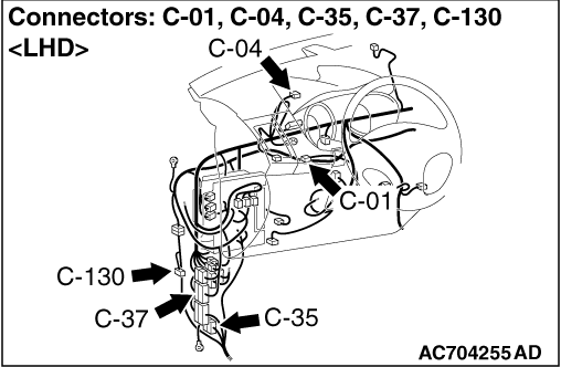
(1)Disconnect joint connector (CAN2), and measure at the wiring harness side.
|
|
|
(2)Resistance between C-04 joint connector (CAN2) terminal No.5 and body earth
OK: 1 kΩ or more
|
|
|
(3)Resistance between C-04 joint connector (CAN2) terminal No.16 and body earth
OK: 1 kΩ or more
|
|
|
Q.
Is the check result normal?
|
|
|
YES <vehicles without ASC> : Go to Step 3. : Go to Step 3.
|
|
|
|
|
|
YES <vehicles with ASC> : Go to Step 2.
|
|
|
|
|
|
NO (the check result is not normal.) : Go to Step 7.
|
|
|
|
|
|
(1)Disconnect joint connector (CAN2), and measure at the wiring harness side.
|
|
|
(2)Resistance between C-04 joint connector (CAN2) terminal No.4 and body earth
OK: 1 kΩ or more
|
|
|
(3)Resistance between C-04 joint connector (CAN2) terminal No.15 and body earth
OK: 1 kΩ or more
|
|
|
Q.
Is the check result normal?
|
|
|
(1)Disconnect joint connector (CAN2), and measure at the wiring harness side.
|
|
|
(2)Resistance between C-04 joint connector (CAN2) terminal No.6 <LHD> or 7 <RHD>
and body earth
OK: 1 kΩ or more
|
|
|
(3)Resistance between C-04 joint connector (CAN2) terminal No.19 <LHD> or 20 <RHD>
and body earth
OK: 1 kΩ or more
|
|
|
Q.
Is the check result normal?
|
|
|
(1)Disconnect joint connector (CAN3), and measure at the wiring harness side.
|
|
|
(2)Resistance between C-01 joint connector (CAN3) terminal No.4 and body earth
OK: 1 kΩ or more
|
|
|
(3)Resistance between C-01 joint connector (CAN3) terminal No.15 and body earth
OK: 1 kΩ or more
|
|
|
Q.
Is the check result normal?
|
|
|
YES <A/T, CVT> : Go to Step 5.
|
|
|
|
|
|
YES <M/T> : Go to Step 6.
|
|
|
|
|
|
(1)Disconnect joint connector (CAN3), and measure at the wiring harness side.
|
|
|
(2)Resistance between C-01 joint connector (CAN3) terminal No.7 and body earth
OK: 1 kΩ or more
|
|
|
(3)Resistance between C-01 joint connector (CAN3) terminal No.20 and body earth
OK: 1 kΩ or more
|
|
|
Q.
Is the check result normal?
|
|
|
(1)Disconnect joint connector (CAN3), and measure at the wiring harness side.
|
|
|
(2)Resistance between C-01 joint connector (CAN3) terminal No.6 and body earth
OK: 1 kΩ or more
|
|
|
(3)Resistance between C-01 joint connector (CAN3) terminal No.19 and body earth
OK: 1 kΩ or more
|
|
|
Q.
Is the check result normal?
|
|
|
 Check C-37 intermediate connector, and repair if necessary. If the intermediate
connector is in good condition, repair the wiring harness between C-04 joint connector (CAN2)
and C-01 joint connector (CAN3). Check C-37 intermediate connector, and repair if necessary. If the intermediate
connector is in good condition, repair the wiring harness between C-04 joint connector (CAN2)
and C-01 joint connector (CAN3).
|
|
|
|
|
|
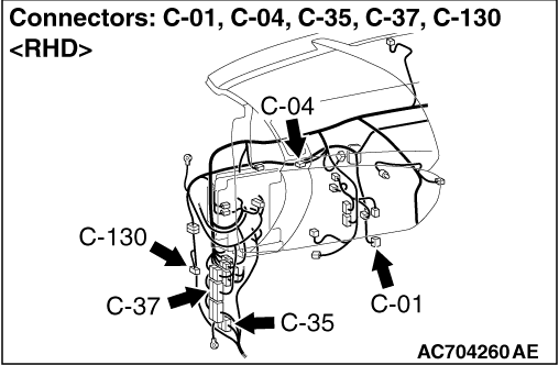
Disconnect C-130 4WD-ECU connector, and diagnose the CAN bus line.
|
|
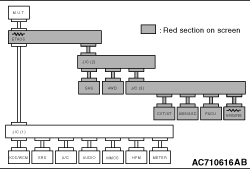
OK: The display of the M.U.T.-III is as shown in the figure.
Q.
Does M.U.T.-III screen correspond to the illustration?
Check C-35 intermediate connector, and repair if necessary. If the intermediate
connector is in good condition, repair the wiring harness between C-130 4WD-ECU connector and
C-04 joint connector (CAN2).
 Check the 4WD-ECU connector, and repair if necessary. If the 4WD-ECU connector
is in good condition, replace the 4WD-ECU. Check the 4WD-ECU connector, and repair if necessary. If the 4WD-ECU connector
is in good condition, replace the 4WD-ECU.
|
|
|
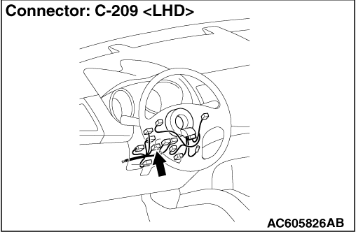
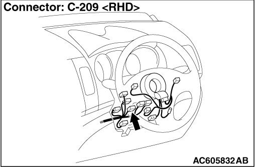
Disconnect C-209 steering wheel sensor connector, and diagnose the CAN bus line.
|
|
OK: The display of the M.U.T.-III is as shown in the figure.
Q.
Does M.U.T.-III screen correspond to the illustration?
Repair the wiring harness between C-209 steering wheel sensor connector and C-04
joint connector (CAN2).
Check the steering wheel sensor connector, and repair if necessary. If the steering
wheel sensor connector is in good condition, replace the steering wheel sensor.
|
|
|
Disconnect C-301 ETACS-ECU connector, and diagnose the CAN bus line.
|
|
OK: The display of the M.U.T.-III is as shown in the figure.
Q.
Does M.U.T.-III screen correspond to the illustration?
Repair the wiring harness between C-301 ETACS-ECU connector and C-04 joint connector
(CAN2).
Check the ETACS-ECU connector, and repair if necessary. If the ETACS-ECU connector
is in good condition, ETACS-ECU.
|
|
|
Disconnect B-06 engine-ECU connector <2000> or B-18 engine-ECU connector <2200>
or B-30 engine-ECU connector <2400, 3000>, and diagnose the CAN bus line.
|
|
OK: The display of the M.U.T.-III is as shown in the figure.
Q.
Does M.U.T.-III screen correspond to the illustration?
Repair the wiring harness between B-06 engine-ECU connector <2000> or B-18
engine-ECU connector <2200> or B-30 engine-ECU connector <2400, 3000> and C-01 joint
connector (CAN3).
Check the engine-ECU connector, and repair if necessary. If the engine-ECU connector
is in good condition, replace the engine-ECU.
|
|
|
Disconnect C-136 CVT-ECU connector <CVT> or C-138 A/T-ECU connector <A/T>, and
diagnose the CAN bus line.
|
|
OK: The display of the M.U.T.-III is as shown in the figure.
Q.
Does M.U.T.-III screen correspond to the illustration?
Repair the wiring harness between C-136 CVT-ECU connector <CVT> or C-138 A/T-ECU
connector <A/T> and C-01 joint connector (CAN3).
Check the CVT-ECU connector <CVT> or A/T-ECU connector <A/T>, and repair
if necessary. If the CVT-ECU connector <CVT> or A/T-ECU connector <A/T> is in good condition,
replace the CVT-ECU <CVT> or A/T-ECU <A/T>.
|
|
|
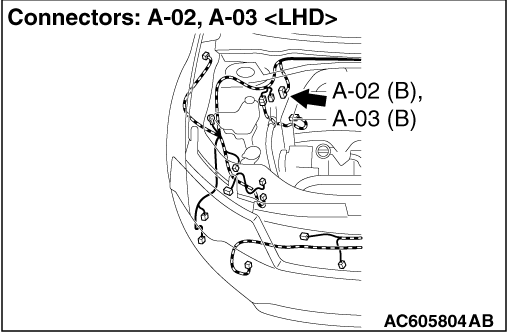
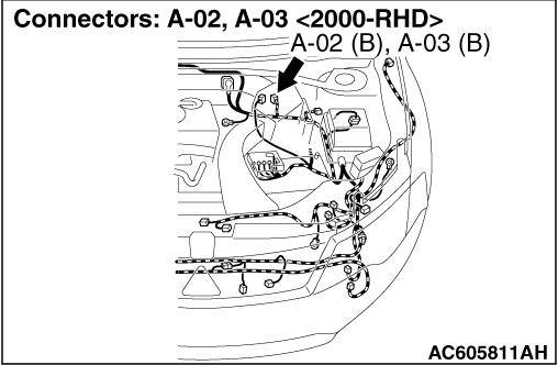
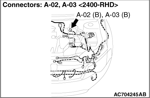
Disconnect A-02 ABS-ECU connector <vehicles without ASC> or A-03 ASC-ECU connector <vehicles
with ASC>, and diagnose the CAN bus line.
|
|
OK: The display of the M.U.T.-III is as shown in the figure.
Q.
Does M.U.T.-III screen correspond to the illustration?
Repair the wiring harness between A-02 ABS-ECU connector <vehicles without
ASC> or A-03 ASC-ECU connector <vehicles with ASC> and C-01 joint connector (CAN3).
Check the ABS-ECU <vehicles without ASC> or ASC-ECU <vehicles with ASC>
connector, and repair if necessary. If the ABS-ECU <vehicles without ASC> or ASC-ECU <vehicles
with ASC> connector is in good condition, replace the ABS-ECU <vehicles without ASC> or
ASC-ECU <vehicles with ASC>.
|