GENERAL INFORMATION


  • Electronic control 4WD has been adopted to ensure the on-road performance, achieve lighter and smaller body, and realize better fuel economy.
  • The electronic control 4WD controls the torque of the electronic control coupling located between the propeller shaft and rear differential. This strategy is enabled by varying the torque distribution to the front and rear wheels from the status closer to the front wheel drive to the status closer to the direct coupling 4WD and realizes the optimal drive force according to the various driving conditions.

AIMS OF DEVELOPMENT


FUNCTION


  • The adoption of the electronic control coupling prevents the tight corner braking phenomenon* and satisfies the traction performance.
    note *Tight corner braking indicates the following condition. When the 4WD vehicle turns sharply on a pavement at low speed (ex. parallel parking), the rotational radius of the front and rear wheels differs, and this difference can no longer be compensated by the tyre slippage. At this time, the driver feels as if the brake was applied.
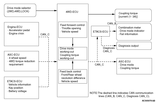
  • The electronic control 4WD receives the signals of the throttle position and vehicle speed via CAN* communication protocol, detects the vehicle driving condition and operation of the driver, and distributes the proper torque to the rear wheels.
    note *: For more information about CAN (Controller Area Network), refer to GROUP 54C .
  • Under severe driving condition, the system is protected by minimising the limitation force of the differential.
  • During high-speed driving, the fuel efficiency is improved by reducing the limitation force of the differential.
  • The following drive modes are available according to the drivers’ preference to provide the enjoyment of selecting functions.
Drive mode
Control content
Appeal point
2WD
Minimises the limitation force of the differential.
High fuel efficiency mode which enables smoother turning performance of the FF vehicle
4WD
Increases the limitation force of the differential according to the different rotation speed of the front and rear wheels and the throttle position.
Universal mode which automatically distributes the drive force to the rear wheels as necessary
LOCK
Further increases the limitation force of the differential compared to the 4WD mode.
Mode which has an excellent driving performance when driving on rough road or in stuck situation and enables the powerful driving


CONSTRUCTION DIAGRAM


System component and function
Parts name
Functional description
Engine ECU
Sends the following signals required by 4WD-ECU via CAN communication.

  • Engine torque signal
  • Throttle position signal
  • Engine speed signal
ABS/ASC-ECU
Sends the following signals required by 4WD-ECU via CAN communication.

  • ABS sensor signal (wheel speed signal) [4 wheels]
  • ABS operation signal
  • 4WD limitation torque signal
Drive mode selector
Sends the drive mode switch signal [2WD/4WD/LOCK] to 4WD-ECU.
ETACS-ECU

  • Receives the drive mode switch signal [2WD/4WD/LOCK] from 4WD-ECU and flashes the indicators (4WD operation indicator and LOCK indicator) in the combination meter.
  • Flashes the indicators (4WD operation indicator and LOCK indicator) in the combination meter in case of failure.

Controls diagnostic function (Compatible with M.U.T.-III).
4WD-ECU
Calculates the optimum differential limitation force judging from the vehicle condition and present drive mode based on the signals from each ECU and switch, and controls the current value flown to the electronic control coupling.
Controls the indicators (4WD operation indicator and LOCK indicator) in the combination meter.
Controls the self-diagnostic function and fail-safe function.
Controls diagnostic function (Compatible with M.U.T.-III).
Electronic control coupling
Transmits the torque corresponding to the current value controlled by 4WD-ECU to the rear wheels.
Drive mode indicator

  • 4WD operation indicator
  • LOCK indicator
Integrated in the combination meter, and indicates the selected drive mode (Not displayed in 2WD mode).

  • When the 4WD operation indicator and LOCK indicator flash alternately, the system automatically enters the front wheel drive mode to protect the drive system components, and the drive mode changeover with the drive mode selector becomes unavailable.
  • When the drive system generates heat, the 4WD operation indicator flashes.
  • The indicator lamp operation signal from 4WD-ECU is sent to the combination meter via ETACS-ECU using CAN communication.
Diagnosis connector
Outputs the diagnosis code and establishes the communication with M.U.T.-III.

System configuration


Control schematic diagram


Electronic control 4WD electric circuit diagram