INSPECTION
VALVE CLEARANCE ADJUSTMENT |
|
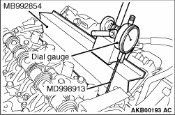 |
1.Install the special tool magnet base plate (MB992854) to the upper face of the cylinder
head at the inlet side. 2.Install the special tool dial gauge extension (MD998913) to the dial gauge. 3.When installing the dial gauge to the magnet base plate, the dial gauge must have almost the same angle as the inlet valve has. |
 |
4.Rotate the crankshaft clockwise and align the timing mark of the rocker shaft holder with
the one circular timing mark of the V.V.T. sprocket. Therefore, the No. 1 cylinder is set at
the top dead centre on its compression stroke. 5.For the No. 1 cylinder inlet valve, adjust the valve clearance according to the following procedures. |
  |
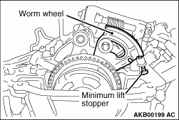
6.
|
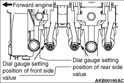 |
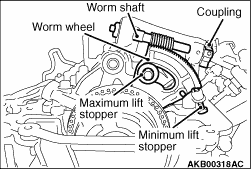
7.Set the dial gauge on the upper face of the valve spring retainer at the forward engine
side. Set the dial gauge to 0.
|
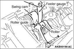 |
8.
|

 |
9.
10.Loosen the rocker arm lock nut at the forward engine side. Pull up the adjusting screw once. From the upper portion of the adjusting screw, sufficiently apply the engine oil between the lower adjusting screw end and the valve axis end so that the engine oil can be provided enough. And then, perform the adjustment by rotating the adjusting screw so that the dial gauge can read -0.11 mm. 11.For the valve at the backward engine side, check the valve clearance in the same procedure as that of the valve at the forward engine side. If the valve clearance is not within the standard value, perform the adjustment in the same procedure as that of the valve at the forward engine side. 12.After the adjustment, hold the driver to prevent the adjustment screw from rotating. Tighten the lock nut to the specified torque. And then, check that the dial gauge reading does not change. Tightening torque: 9.0 ± 1.0 N·m 13.Check again the valve clearance at the forward engine side. If the valve clearance is not within the standard value, perform the adjustment in the same procedure as the first adjustment. 14.After the adjustment, hold the adjusting screw by the driver not to rotate the adjusting screw. Temporarily tighten the lock nut. Rotate the coupling anti-clockwise and return the worm wheel to the middle lift position. Pull out the thickness gauge. Specified torque: 9.0 ± 1.0 N·m 15.For the No. 2 cylinder inlet valve, adjust the valve clearance according to the procedures from Step 7 to Step 14. 16.For the No. 1 and No.3 cylinder exhaust valves, adjust the valve clearance according to the following procedures. 17.Insert the feeler gauge between the exhaust valve axis end and the adjusting screw. Loosen the lock nut. Adjust the valve clearance so that the clearance is within the standard value by rotating the adjusting screw. Standard value: 0.20 ± 0.03 mm 18.After the adjustment, hold the driver to prevent the adjustment screw from rotating. Tighten the lock nut to the specified torque. Tightening torque: 9.0 ± 1.0 N·m 19.Rotate the crankshaft clockwise 1 revolution. Therefore, the No. 4 cylinder is set at the top dead centre on its compression stroke. 20.For the No. 3 cylinder inlet valve, adjust the valve clearance according to the procedures from Step 7 to Step 14. 21.For the No. 4 cylinder inlet valve, adjust the valve clearance according to the procedures from Step 7 to Step 14. 22.For the No. 2 and No. 4 cylinder exhaust valves, adjust the valve clearance according to the procedures from Step 17 to Step 18. |