|
|
1.Raise the vehicle using a jack and support the specified points with a rigid rack.
|
|
|
2.| caution |
Before connecting or disconnecting M.U.T.-III, always turn the ignition switch to the LOCK (OFF) position.
|
Before setting M.U.T.-III, turn the ignition key to the LOCK (OFF) position.
|
|
|
3.Confirm that the selector lever is in the "N" position, and then start the engine.
|
|
|
4.When carrying out the actuator tests No.01 to 04, perform the actuator tests using M.U.T.-III while depressing the brake pedal. When carrying out the actuator tests No.05 to 08, perform the actuator tests using M.U.T.-III without depressing the brake pedal. When carrying out the actuator tests, rotate the wheel by hands to confirm that the braking force changes.
| note |
- While performing the actuator test, the ABS warning lamp flashes at a rate of 2 Hz.
- When ASC-ECU is disabled due to the fail-safe function, the M.U.T.-III actuator test cannot be performed.
- After the actuator test has been performed, the ABS warning lamp, brake waning lamp, ASC ON indicator lamp, and ASC OFF indicator lamp illuminate until the ignition switch is turned to ON again or the communication between M.U.T.-III and ASC-ECU is terminated.
|
|
|
|
5.
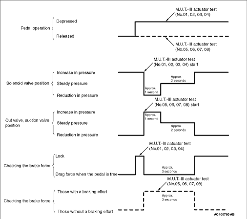
This is indicated as shown in the above.
|
|
|
6.When any malfunction has been found, take a necessary action according to the "Judgement Table."
|
|
|
7.After the inspection, turn the ignition switch to the LOCK (OFF) position, and then disconnect M.U.T.-III.
|
|
|
1.Operate the pre-removal steps for the hydraulic unit. (Refer to  .) .)
|
|
|
2.Remove all brake tubes.
|
|
|
3.Remove the protector. <RHD>
|
|
|
4.Loosen the mounting bolt and nut of the hydraulic unit bracket.
|
|
|
5.Install all brake tubes temporarily.
|
|
|
6.Shake hydraulic unit to all directions with both hands to make the hydraulic unit bracket insulator fit with the unit.
|
|
|
7.Install the hydraulic unit bracket with mounting bolt and nut not to load the brake tube.
|
|
|
8.Install the protector. <RHD>
|
|
|
9.Install all brake tubes securely.
| note |
Install the flare nut taking care not to let the brake tube turn together.
|
|
|
|
10.Operate the post-installation steps of the hydraulic unit. (Refer to .)
|