|
|
Use M.U.T.-III to diagnose the CAN bus lines.
|
|
|
Q.
Is the check result normal?
|
|
|
 Repair the CAN bus line (Refer to GROUP 54C - Troubleshooting Repair the CAN bus line (Refer to GROUP 54C - Troubleshooting  ). ).
|
|
|
|
|
|
(1)Connect the negative battery terminal.
|
|
|
(2)After erasing the diagnosis code memory, check the diagnosis code again.
|
|
|
(3)Disconnect the negative battery terminal.
|
|
|
Q.
Is the diagnosis code No. B1453 set?
|
|
|
Intermittent malfunction (Refer to GROUP 00 - How to Use Troubleshooting/Inspection
Service Points - How to Cope with Intermittent Malfunction ).
|
|
|
|
|
|
(1)Check that the negative battery terminal is disconnected. If connected, disconnect
the negative battery terminal.
|
|
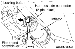
(2)Use the flat-tipped screwdriver to pull out the locking button of left curtain air bag
module connector to the direction of the arrow. After releasing the lock, disconnect the connector.
|
|
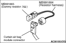
(3)Connect the dummy resistor (Special tool: MB991865) to the resistor harness (Special tool:
MB991884).
(4)Connect the resistor harness (special tool) to left curtain air bag module (front)
connector.
(5)Connect the negative battery terminal.
(6)After erasing the diagnosis code memory, check the diagnosis code again.
(7)Disconnect the negative battery terminal.
Q.
Is diagnosis code No. B1453 set?
 Go to Step 4. Go to Step 4.
Replace the left curtain air bag module (Refer to .)
|
|
|
(1)Check that the negative battery terminal is disconnected. If the negative battery
terminal is connected, disconnect it.
|
|
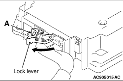
(2)While pushing the part "A" indicated in the figure of the harness side connector, turn
the lock lever to the direction of the arrow to release the lock lever, and disconnect the SRS-ECU
connector.
|
|
(3)| danger |
To release SRS-ECU wiring harness side connector short spring in the
following operations, disconnect curtain air bag module connector in advance, and keep the squib
circuit shorted.
|
Use the flat-tipped screwdriver to pull out the locking button of left curtain air bag
module connector to the direction of the arrow. After releasing the lock, disconnect the connector.
|
|
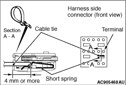
(4)| caution |
The short spring may not be released due to the insufficient insertion. Therefore, insert
the insulator for 4 mm or more.
|
Insert an insulator (width: 3 mm, thickness: 0.5 mm) such as cable tie between the CLS+,
CLS- line and the short spring, and release the short spring.
(5)Connect the negative battery terminal.
(6)Ignition switch: ON
(7)Measure the voltage between the SRS-ECU harness side connector CLS+, CLS-
line and the body earth.
OK: 1 V or less
(8)Disconnect the negative battery terminal.
Q.
Is the check result normal?
Go to Step 5.
Repair the wiring harness.
|
|
|
Q.
Is the diagnosis code No. B1453 set?
|
|
|
Replace SRS-ECU (Refer to ).
|
|
|
|
|
|
Intermittent Malfunction (Refer to GROUP 00 - How to Use Troubleshooting/Inspection
Service Points - How to Cope with Intermittent Malfunction ).
|
|
|
|