|
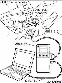
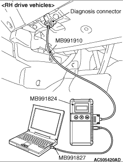
Connect the M.U.T.-III to the 16-pin diagnosis connector, and read the diagnosis code.
| note |
For details on how to use the M.U.T.-III, refer to the "M.U.T.-III operation manual."
|
- Ensure that the ignition switch is at the LOCK (OFF)
position.
- Start up the personal computer.
- Connect special tool M.U.T.-III USB cable (MB991827) to V.C.I. (MB991824) and the
personal computer.
- Connect M.U.T.-III main harness A (MB991910) to the V.C.I.
- Connect M.U.T.-III main harness A to the diagnosis connector of the vehicle.
- Turn the V.C.I. power switch to the ON position.
| note |
When the V.C.I. is energized, the V.C.I. indicator lamp will be illuminated in a green colour.
|
- Start the M.U.T.-III system on the PC and turn the ignition switch to the ON position.
- Read the diagnosis code.
- Disconnecting the M.U.T.-III is the reverse of the connecting sequence, making sure
that the ignition switch is at the LOCK (OFF) position.
| note |
The ABS warning lamp may flash when the ignition switch is turned ON with the M.U.T.-III connected.
This is because the diagnosis display function of the ABS warning lamp is activated by grounding
the diagnosis connector terminal No.1, and is not detrimental in any way.
|
|
|
Connect the M.U.T.-III to the diagnosis connector, and erase the diagnosis code. The procedure
is the same as "HOW TO READ DIAGNOSIS CODE ". ".
|
|
|
1.Turn the ignition switch to the "LOCK" (OFF) position.
|
|
|
2.Disconnect the negative battery cable, wait for at least 10 minutes, and then reconnect
it.
|
|
|
3.Start the engine and let it run at idle for 10 minutes.
|
|
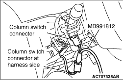
1.Remove the steering column cover.
2.Remove the steering column switch connector.
3.Connect special tool SWS monitor harness (for column-ECU) MB991812.
|
|
1.Connect the special tool Intermediate wires (MB991960) for SWS monitor customisation to
the special tool M.U.T.-III main harness A (MB991910).
2.Connect the M.U.T.-III main harness A (with the intermediate wires) to the special
tool V.C.I. (MB991824) .
3.Connect the intermediate wires for SWS monitor customisation to the diagnosis
connector and the SWS monitor cartridge.
|
|
1.Connect the M.U.T.-III to the diagnosis connector, and erase the diagnosis code.
2.If the M.U.T.-III buzzer sounds once when each switch is operated (ON/OFF),
the input signal for that switch circuit system is normal.
|
|
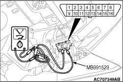
1.Use the special tool diagnosis code check harness (MB991529) to connect the ETACS terminal
(terminal 9) and the earth terminals (terminals 4 and 5) of the diagnosis connector to the voltmeter.
2.If the needle of the voltmeter flickers once when each switch is operated (ON/OFF),
the input signal for that switch circuit system is normal.
|