|
|
Q.
Is the check result normal?
|
|
|
 Repair or replace the connector. Repair or replace the connector.
|
|
|
|
|
|
- Check exhaust gas recirculation valve itself [Refer to GROUP 17 -
Emission
Control System <6G7> -
Exhaust Gas Recirculation System -
exhaust gas
recirculation Valve (stepper motor) Check
 . .
|
|
|
Q.
Is the check result normal?
|
|
|
Replace the exhaust gas recirculation valve (stepper motor).
|
|
|
|
|
|
- Disconnect connector, and measure at harness side.
- Ignition switch: ON
- Voltage between terminal No. 2, No. 5 and earth.
|
|
|
Q.
Is the check result normal?
|
|
|
Q.
Is the check result normal?
|
|
|

Check and repair harness between B-02 (terminal No.
2, No. 5) exhaust gas recirculation valve connector and B-15X (terminal No. 1) engine control
relay connector.
- Check power supply line for open/short circuit.
|
|
|
|
|
|
Repair or replace the connector.
|
|
|
|
|
|
- Disconnect connector, and measure at harness side.
- Ignition switch: ON
- Voltage between terminal No. 3, No. 12, No. 19, No. 26 and earth.
|
|
|
Q.
Is the check result normal?
|
|
|
Q.
Is the check result normal?
|
|
|
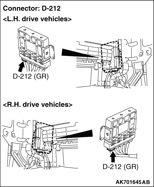
Check and repair harness between B-02 exhaust
gas recirculation valve connector and D-212 engine-A/T-ECU connector.
- Check harness between B-02 (terminal No. 1) exhaust
gas recirculation valve connector and D-212 (terminal No. 3) engine-A/T-ECU connector.
- Check harness between B-02 (terminal No. 3) exhaust gas recirculation valve connector
and D-212 (terminal No. 12) engine-A/T-ECU connector.
- Check harness between B-02 (terminal No. 4) exhaust gas recirculation valve connector
and D-212 (terminal No. 19) engine-A/T-ECU connector.
- Check harness between B-02 (terminal No. 6) exhaust gas recirculation valve connector
and D-212 (terminal No. 26) engine-A/T-ECU connector.
- Check power supply line for open/short circuit.
|
|
|
|
|
|
Repair or replace the connector.
|
|
|
|
|
|
Q.
Is the check result normal?
|
|
|
Repair or replace the connector.
|
|
|
|
|
|
- Check harness between B-02 (terminal No. 1) exhaust
gas recirculation valve connector and D-212 (terminal No. 3) engine-A/T-ECU connector.
- Check harness between B-02 (terminal No. 3) exhaust gas recirculation valve connector
and D-212 (terminal No. 12) engine-A/T-ECU connector.
- Check harness between B-02 (terminal No. 4) exhaust gas recirculation valve connector
and D-212 (terminal No. 19) engine-A/T-ECU connector.
- Check harness between B-02 (terminal No. 6) exhaust gas recirculation valve connector
and D-212 (terminal No. 26) engine-A/T-ECU connector.
|
|
|
- Check output line for damage.
|
|
|
Q.
Are the check results normal?
|
|
|
Repair the damaged harness wire.
|
|
|
|
|
|
Q.
Is the check result normal?
|
|
|
Repair or replace the connector.
|
|
|
|
|
|
- Check power supply line for damage.
|
|
|
Q.
Is the check result normal?
|
|
|
Replace the engine-A/T-ECU.
|
|
|
|
|
|
Repair the damaged harness wire.
|
|
|
|