Code No. P2135: Throttle Position Sensor (Main and Sub) Range/Performance Problem
OPERATION
- Refer to Code No. P0122: Throttle Position Sensor (main)
Circuit Low Input
 .
. - Refer to Code No. P0222: Throttle Position Sensor (sub) Circuit Low Input .
FUNCTION
- Engine-A/T-ECU checks the throttle position sensor output
signal characteristics for abnormal conditions.
TROUBLE JUDGMENT
Check Conditions
- Ignition switch is in "ON" position.
- Throttle position sensor (main) output voltage is 0.2 -
4.8 V.
- Throttle position sensor (sub) output voltage is 0.2 -
4.8 V
- Total output voltage of main and sub throttle position sensors is less than 4.5
V or is more than 5.5 V.
PROBABLE CAUSES
- Failed throttle position sensor
- Harmess damage in throttle position sensor circuit or loose connector contact
- Failed engine-A/T-ECU
DIAGNOSIS PROCEDURE |
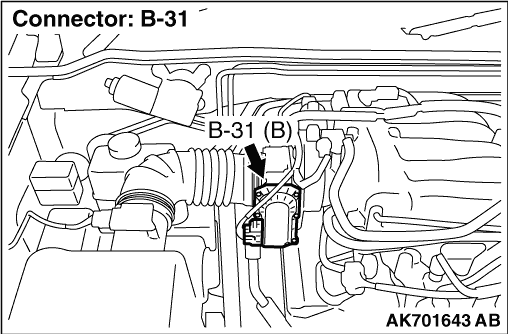
STEP 1. Connector check: B-31 electronic-controlled throttle valve connector |
Q.
Is the check results normal?
|
 Go to Step 2 . Go to Step 2 . |
|
 Repair or replace the connector. Repair or replace the connector. |
|
STEP 2. Perform resistance measurement at B-31 electronic-controlled throttle valve connector. |
|
| OK: Continuity (2 Ω
or less) |
Q.
Is the check result normal?
|
| Go to Step 6 . |
|
| Go to Step 3 . |
|
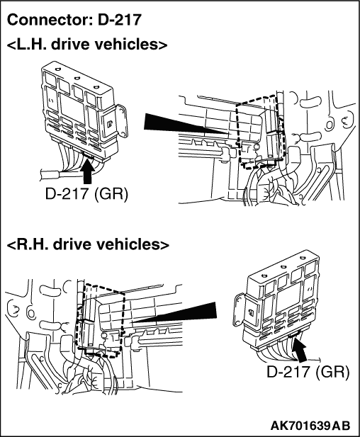
STEP 3. Connector check: D-217 engine-A/T-ECU connector |
Q.
Is the check result normal?
|
| Go to Step 4 . |
|
| Repair or replace the connector. |
|
STEP 4. Check harness between B-31 (terminal No. 4) electronic-controlled throttle valve connector and D-217 (terminal No. 105) engine-A/T-ECU connector. |
|
Q.
Is the check result normal?
|
| Go to Step 5 . |
|
| Repair the damaged harness wire. |
|
STEP 5. Check the trouble symptoms |
Q.
Does trouble symptom persist?
|
| Replace the engine-A/T-ECU. |
|
| Intermittent malfunction (Refer to GROUP 00 -
How to Use Troubleshooting/Inspection
Service Points -
How to Cope with Intermittent Malfunctions ). |
|
STEP 6. Connector check: D-217 engine-A/T-ECU connector |
Q.
Is the check result normal?
|
| Go to Step 7 . |
|
| Repair or replace the connector. |
|
STEP 7. Check harness between B-31 (terminal No. 2) electronic-controlled throttle valve connector and D-217 (terminal No. 106) engine-A/T-ECU connector. |
|
Q.
Is the check result normal?
|
| Go to Step 8 . |
|
| Repair the damaged harness wire. |
|
STEP 8. Check harness between B-31 (terminal No. 1) electronic-controlled throttle valve connector and D-217 (terminal No. 115) engine-A/T-ECU connector. |
|
Q.
Is the check result normal?
|
| Go to Step 9 . |
|
| Repair the damaged harness wire. |
|
STEP 9. Check harness between B-31 (terminal No. 3) electronic-controlled throttle valve connector and D-217 (terminal No. 113) engine-A/T-ECU connector. |
|
Q.
Is the check result normal?
|
| Go to Step 10 . |
|
| Repair the damaged harness wire. |
|
STEP 10. Replace the throttle body assembly. |
|
Q.
Does trouble system persist?
|
| Replace the engine-A/T-ECU. |
|
| Check end. |
|