Code No. P0108: Manifold Absolute Pressure Sensor Circuit High Input


OPERATION
- A power voltage of 5 V is applied to the manifold absolute
pressure sensor power terminal (terminal No. 3) from the engine-A/T-ECU (terminal No. 97) and
earthed to the engine-A/T-ECU (terminal No. 96) from the manifold absolute pressure sensor (terminal
No. 2).
- The sensor signal is inputted to the engine-A/T-ECU (terminal No. 101) from the
manifold absolute pressure sensor output terminal (terminal No. 1).
FUNCTION
- The manifold absolute pressure sensor detects a change
in intake pipe pressure and inputs the signal to the engine-A/T-ECU.
- In response to the signal, the engine-A/T-ECU corrects the fuel injection amount,
etc.
TROUBLE JUDGMENT
Check Condition
- 2 seconds later from when the ignition switch is in "ON" position or the engine
starts
- The manifold absolute pressure sensor output voltage is more than 4.5 V (Barometric
pressure of above 114 kPa or equivalent) for 2 seconds.
PROBABLE CAUSES
- Failed manifold absolute pressure sensor
- Open circuit in manifold absolute pressure sensor circuit or loose connector contact
- Failed engine-A/T-ECU
DIAGNOSIS PROCEDURE |
STEP 1. M.U.T.-III data list |
|
Q.
Is the check result normal?
|
 Intermittent malfunction (Refer to GROUP 00 -
How to Use Troubleshooting/Inspection
Service Points -
How to Cope with Intermittent Malfunctions Intermittent malfunction (Refer to GROUP 00 -
How to Use Troubleshooting/Inspection
Service Points -
How to Cope with Intermittent Malfunctions  ). ). |
|
 Go to Step 2 . Go to Step 2 . |
|
STEP 2. Connector check: B-05 manifold absolute pressure sensor connector |
Q.
Is the check result normal?
|
| Go to Step 3 . |
|
| Repair or replace the connector. |
|
STEP 3. Perform resistance measurement at B-05 manifold absolute pressure sensor connector. |
|
| OK: Continuity (2 Ω
or less) |
Q.
Is the check result normal?
|
| Go to Step 7 . |
|
| Go to Step 4 . |
|
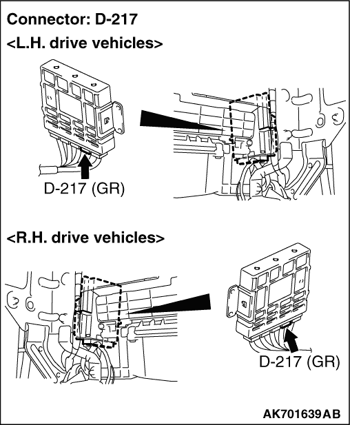
STEP 4. Connector check: D-217 engine-A/T-ECU connector |
Q.
Is the check result normal?
|
| Go to Step 5 . |
|
| Repair or replace the connector. |
|
STEP 5. Check harness between B-05 (terminal No. 2) manifold absolute pressure sensor connector and D-217 (terminal No. 96) engine-A/T-ECU connector. |
|
|
Q.
Is the check result normal?
|
| Go to Step 6 . |
|
| Repair the damaged harness wire. |
|
STEP 6. M.U.T.-III data list |
|
Q.
Is the check result normal?
|
| Intermittent malfunction (Refer to GROUP 00 -
How to Use Troubleshooting/Inspection
Service Points -
How to Cope with Intermittent Malfunctions ). |
|
| Replace the engine-A/T-ECU. |
|
STEP 7. M.U.T.-III data list |
|
Q.
Is the check result normal?
|
| Intermittent malfunction (Refer to GROUP 00 -
How to Use Troubleshooting/Inspection
Service Points -
How to Cope with Intermittent Malfunctions ). |
|
| Replace the manifold absolute pressure sensor. |
|