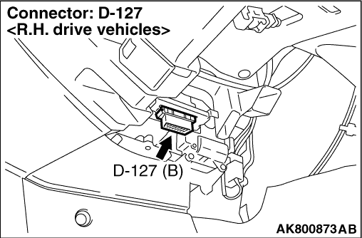
|
- Connect the M.U.T.-III to the diagnosis connector.
Q.
Is the V.C.I. indicator lamp illuminates in a green colour?
 CAN bus diagnosis (Refer to GROUP 54D -
Troubleshooting -
Can
Bus Diagnosis Table CAN bus diagnosis (Refer to GROUP 54D -
Troubleshooting -
Can
Bus Diagnosis Table  ). ).
 Go to Step 2 . Go to Step 2 .
|
|
|
Q.
Is the check result normal?
|
|
|
- Voltage between terminal No. 16 and earth.
|
|
|
Q.
Is the check result normal?
|
|
|
Check intermediate connectors D-404, D-405, and repair if necessary. If intermediate
connectors are normal, check and repair harness between D-127 (terminal No. 16) diagnosis connector
and battery.
|
|
|
|
|
|
- Disconnect connector.
- Check open circuit between terminal No. 4 and earth also between terminal No. 5
and earth.
|
|
|
Q.
Is the check result normal?
|
|
|
Refer to M.U.T.-III User’s Manual -
Troubleshooting Procedures.
|
|
|
|
|
|
Repair harness between diagnosis connector and body earth.
|
|
|
|