REMOVAL AND INSTALLATION <6G7>


Pre-removal Operation
  • Fuel Line Pressure Reduction [Refer to GROUP 13A - On-vehicle Service, Fuel Pump Connector Disconnection (How to Reduce Pressurized Fuel Lines) ].
  • Engine Coolant Draining (Refer to GROUP 14 - On-vehicle Service, Engine Coolant Replacement ).
  • Air Cleaner Assembly Removal (Refer to ).
  • Throttle Body Assembly Removal (Refer to GROUP 13A - Throttle Body Assembly ).
  • EGR Valve Removal (Refer to GROUP 17 - Emission Control, EGR Valve ).

Post-installation Operation
  • EGR Valve Installation (Refer to GROUP 17 - Emission Control, EGR Valve ).
  • Throttle Body Assembly Installation (Refer to GROUP 13A - Throttle Body Assembly ).
  • Air Cleaner Assembly Installation (Refer to ).
  • Engine Coolant Refilling (Refer to GROUP 14 - On-vehicle Service, Engine Coolant Replacement ).
  • Fuel Leak Check


Removal steps


1.
Purge control solenoid valve connector


2.
Purge control solenoid valve


3.
Manifold absolute pressure sensor connector


4.
Manifold absolute pressure sensor


5.
O-ring


6.
Noise condenser connector


7.
Noise condenser


8.
Variable induction control solenoid valve connector


9.
Control wiring harness and detonation sensor wiring harness combination connector


10.
Detonation sensor wiring harness connector


11.
Control wiring harness and injector wiring harness (L.H.) combination connector


12.
Injector wiring harness (L.H.) connector


13.
Earth cable


14.
Harness clamp


15.
Harness bracket


16.
Control wiring harness and injector wiring harness (R.H.) combination connector


17.
Injector wiring harness (R.H.) connector


18.
Vacuum hose connection


19.
Fuel vapour control hose


20.
Emission vacuum control chamber


21.
Fuel vapour control hose


22.
Fuel vapour control hose connection


23.
Emission vacuum pipe


24.
Emission control equip hose


25.
Emission vacuum hose


26.
Emission control vacuum tank


27.
Emission control equip hose


28.
Variable induction control solenoid valve assembly


29.
Emission vacuum hose


30.
Emission vacuum hose


31.
PCV hose connection


32.
Emission vacuum pipe


33.
Exhaust manifold EGR pipe assembly

>>E<<
34.
Exhaust manifold EGR pipe gasket


35.
Surge tank stay
<<A>>
>>D<<
36.
Surge tank assembly

>>D<<
37.
Surge tank gasket


38.
Engine air intake surge tank


39.
Intake manifold tuning valve gasket S


40.
Intake manifold tuning valve gasket P


41.
Harness bracket


Removal steps
<<B>>
>>C<<
42.
Fuel high-pressure hose connection


43.
Cooling water line hose connection


44.
Cooling water line hose connection


45.
Injector connector
<<C>>

46.
Fuel delivery pipe, fuel high-pressure hose and injector assembly


47.
Oil pipe connection

>>B<<
48.
Inlet manifold

>>A<<
49.
Inlet manifold gasket

REMOVAL SERVICE POINTS


<<A>> SURGE TANK ASSEMBLY REMOVAL


If the clearance is too narrow when removing the surge tank, jack up the transmission assembly to secure a working space.

<<B>> FUEL HIGH-PRESSURE HOSE DISCONNECTION


1.
caution Be careful not to twist the fuel high-pressure hose because it is made of resin.
Insert the (-) driver or similar tool (width: 6 mm, thickness: 1 mm) to the retainer of the fuel high-pressure hose connector.

2.Turn the (-) driver inserted into the retainer by 90 degrees, push up the retainer, and then unlock the fuel high-pressure hose connector.
3.Disconnect the fuel high-pressure hose from the fuel delivery pipe.

<<C>> FUEL DELIVERY PIPE, FUEL HIGH-PRESSURE HOSE AND FUEL INJECTOR ASSEMBLY REMOVAL


caution Do not drop the fuel injector.
Remove the fuel delivery pipe and fuel high-pressure hose with the fuel injector assembly attached to it.

INSTALLATION SERVICE POINTS


>>A<< INLET MANIFOLD GASKET INSTALLATION


Install the inlet manifold gasket with the protrusions in the position illustrated.

>>B<< INLET MANIFOLD INSTALLATION


Tighten the inlet manifold mounting nuts by the following procedure.
Order
Mounting nuts
Tightening torque
1st
Right bank nuts
6.5 ± 1.0 N·m
2nd
Left bank nuts
22 ± 1 N·m
3rd
Right bank nuts
22 ± 1 N·m
4th
Left bank nuts
22 ± 1 N·m
5th
Right bank nuts
22 ± 1 N·m

>>C<< FUEL HIGH-PRESSURE HOSE CONNECTION


1.Pull up the lock of fuel high-pressure hose to unlock before installing.

2.
caution After connecting the fuel high-pressure hose, slightly pull it in the pull-out direction to check that it is installed firmly. In addition, check that there is approximately 1 mm play.
Install the fuel high-pressure hose to the fuel delivery pipe securely and push the lock of fuel high-pressure hose downward and lock thoroughly.

>>D<< SURGE TANK GASKET/SURGE TANK ASSEMBLY INSTALLATION


1.Temporarily install the positioning bolt for the surge tank gasket (M8×1.25 mm, length 25 mm) to the position shown in the figure from under side.

2.Install the surge tank gasket with the protrusions in the position illustrated.
3.Install the surge tank assembly taking care not to let the surge tank gasket deviate from its position.
4.Remove the positioning bolt for surge tank gasket that was temporarily installed in step 1.

>>E<< EXHAUST MANIFOLD EGR PIPE GASKET INSTALLATION


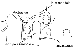
Install the exhaust manifold EGR pipe gasket as its protrusion is in the direction shown.