|
|
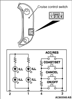
1.Remove the cruise control switch (Refer to  ). ).
|
|
2.Measure the resistance between terminal No.3 and terminal No.4 when each of the" ON/OFF", "CANCEL", "COAST/SET" and "ACC/RES" switches is pressed. If the values measured at the time each switch is pressed correspond to those in the table below, the resistance values are correct.
|
|
Terminal connector of tester
|
Switch position
|
Specified condition
|
3 - 4
|
All switches are released.
|
Open circuit
|
"ON/OFF" switch is pressed
|
Continuity (less than 2 ohms)
|
"CANCEL" switch is pressed
|
202.5 - 208 Ω
|
"COAST/SET" switch is pressed
|
610.5 - 624.5 Ω
|
"ACC/RES" switch is pressed
|
1838 - 1877 Ω
|
|
3.Check that illumination of the cruise control switch turns on when the battery positive terminal is connected to cruise control switch connector terminal No.2, and the battery negative terminal is connected to cruise control switch connector terminal No.1.
|
|
|
Refer to GROUP 35A - Brake Pedal, Inspection, Stop Lamp Switch Check .
|
|
|
Refer to GROUP 21A - Clutch Pedal, Inspection, Clutch Switch Continuity Check .
|
|
|
Refer to GROUP 23A - On-vehicle Service, Essential Service, Inhibitor Switch Continuity Check . <6G7>
|
|
|
Refer to GROUP 23C - On-vehicle Service, Essential Service, Inhibitor Switch Continuity Check . <4M4>
|
|
|
Refer to GROUP 13A - On-vehicle Service, Throttle Valve Control Servo Check .
|