Code No.P1571: Malfunction of the Stop Lamp Switch System.


OPERATION
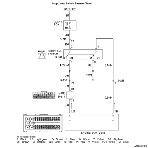
- Battery positive voltage is supplied to the stop lamp switch (terminal No.2 and No.4.)
- When the brake pedal is depressed, battery positive voltage is applied to the engine-ECU terminal No.125 and No.126.
DIAGNOSIS CODE SET CONDITIONS
Check Condition
- The cruise control indicator lamp illuminates.
Judgement Criteria
- Open/short in stop lamp switch circuit.
- Open circuit in the brake switch circuit (between engine-ECU terminal No.126 and earth.)
PROBABLE CAUSES
- Damaged harness or connector.
- Malfunction of the stop lamp switch.
- Malfunction of the engine-ECU.
|
|
STEP 1. Check the data list.
|
|
|
Using M.U.T.-III, check the data list (Refer to  - data list reference table.) - data list reference table.)
|
|
|
- Item 135: Stop lamp switch.
|
|
|
Q.
Is the check result normal?
|
|
|
 Go to Step 13. Go to Step 13.
|
|
|
|
|
|
 Go to Step 2. Go to Step 2.
|
|
|
|
|
|
STEP 2. Check the stop lamp operation.
|
|
|
Check the stop lamp operation.
|
|
|
OK:
Brake pedal depressed: Stop lamp will illuminate.
Brake pedal not depressed: Stop lamp does not illuminate.
|
|
|
Q.
Is the check result normal?
|
|
|
Go to Step 3.
|
|
|
|
|
|
Go to Step 5.
|
|
|
|
|
|
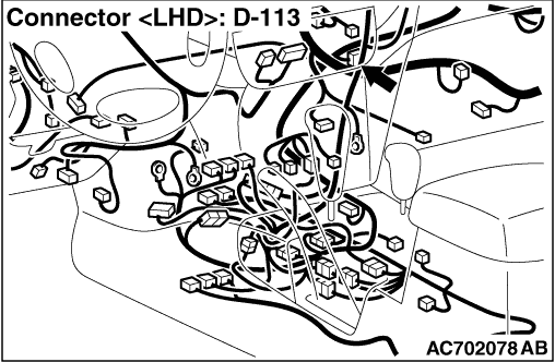
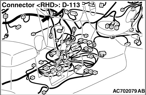
STEP 3. Connectors check: D-215 engine-ECU connector, D-230 intermediate connector and D-113 J/C (6).
|
|
|
Q.
Is the check result normal?
|
|
|
Go to Step 4.
|
|
|
|
|
|
Repair or replace the damaged connector. Then go to Step 21.
|
|
|
|
|
|
STEP 4. Check the harness wire between engine-ECU connector D-215 terminal No.125 and stop lamp switch connector D-134 terminal No.1.
|
|
|
Q.
Is the check result normal?
|
|
|
Go to Step 12.
|
|
|
|
|
|
Repair the damaged harness wire. Then go to Step 21.
|
|
|
|
|
|
STEP 5. Measure the voltage at stop lamp switch connector D-134.
|
|
|
(1)Disconnect stop lamp switch connector D-134 and measure at the harness connector side.
|
|
|
(2)Measure the voltage between stop lamp switch connector D-134 terminal No.2 and earth.
OK: System voltage
|
|
|
(3)Connect stop lamp switch connector D-134.
|
|
|
Q.
Is the check result normal?
|
|
|
Go to Step 9.
|
|
|
|
|
|
Go to Step 6.
|
|
|
|
|
|
STEP 6. Connectors check: D-134 stop lamp switch connector and D-241 intermediate connector.
|
|
|
Q.
Is the check result normal?
|
|
|
Go to Step 7.
|
|
|
|
|
|
Repair or replace the damaged connector. Then go to Step 21.
|
|
|
|
|
|
STEP 7. Check the harness wire between stop lamp switch connector D-134 terminal No.2 and fuse No.16 at the relay box in engine compartment.
|
|
|
Q.
Is the check result normal?
|
|
|
Go to Step 8.
|
|
|
|
|
|
Repair the damaged harness wire. Then go to Step 21.
|
|
|
|
|
|
STEP 8. Check the fuse No.16 at the relay box in engine compartment.
|
|
|
Q.
Is the check result normal?
|
|
|
Go to Step 12.
|
|
|
|
|
|
Check the stop lamp system harness and replace the fuse. Then go to Step 21.
|
|
|
|
|
|
STEP 9. Connector check: D-134 stop lamp switch connector.
|
|
|
Q.
Is the check result normal?
|
|
|
Go to Step 10.
|
|
|
|
|
|
Repair or replace the damaged connector. Then go to Step 21.
|
|
|
|
|
|
STEP 10. Check the harness wire between stop lamp switch connector D-134 terminal No.1 and intermediate connector D-230 terminal No.10.
|
|
|
Q.
Is the check result normal?
|
|
|
Go to Step 11.
|
|
|
|
|
|
Repair the damaged harness wire. Then go to Step 21.
|
|
|
|
|
|
STEP 11. Check the stop lamp switch.
|
|
|
(1)Remove the stop lamp switch (Refer to GROUP 35A - Brake Pedal .)
|
|
|
(2)Check for continuity between the stop lamp switch terminals (Refer to GROUP 35A - Brake Pedal, Stop Lamp Switch Check .)
|
|
|
Q.
Is the check result normal?
|
|
|
Install the stop lamp switch (Refer to GROUP 35A - Brake Pedal .) Then go to Step 12.
|
|
|
|
|
|
Replace the stop lamp switch (Refer to GROUP 35A - Brake Pedal .) Then go to Step 21.
|
|
|
|
|
|
STEP 12. Check the data list.
|
|
|
Using M.U.T.-III, check the data list (Refer to - data list reference table.)
|
|
|
- Item 135: Stop lamp switch.
|
|
|
Q.
Is the check result normal?
|
|
|
Go to Step 13.
|
|
|
|
|
|
Replace the engine-ECU (Refer to GROUP 13B - Engine-ECU .) Then go to Step 21.
|
|
|
|
|
|
STEP 13. Check the data list.
|
|
|
Using M.U.T.-III, check the data list (Refer to - data list reference table.)
|
|
|
Q.
Is the check result normal?
|
|
|
Go to Step 20.
|
|
|
|
|
|
Go to Step 14.
|
|
|
|
|
|
STEP 14. Measure the terminal voltage at engine-ECU connector D-215.
|
|
|
(1)Turn the ignition switch to the "ON" position.
|
|
|
(2)Do not disconnect the engine-ECU connectors.
|
|
|
(3)Measure the terminal voltage between engine-ECU connector D-215 terminal No.126 and earth with engine-ECU connector connected.
OK:
Brake pedal depressed: System voltage.
Brake pedal not depressed: 1 V or less.
|
|
|
(4)Turn the ignition switch to the "LOCK" (OFF) position.
|
|
|
Q.
Is the check result normal?
|
|
|
Go to Step 19.
|
|
|
|
|
|
Go to Step 15.
|
|
|
|
|
|
STEP 15. Connectors check: D-134 stop lamp switch connector, D-231 intermediate connector and D-215 engine-ECU connector.
|
|
|
Q.
Is the check result normal?
|
|
|
Go to Step 16.
|
|
|
|
|
|
Repair or replace the damaged connector. Then go to Step 21.
|
|
|
|
|
|
STEP 16. Check the harness wire between engine-ECU connector D-215 terminal No.126 and stop lamp switch connector D-134 terminal No.4.
|
|
|
Q.
Is the check result normal?
|
|
|
Go to Step 17.
|
|
|
|
|
|
Repair the damaged harness wire. Then go to Step 21.
|
|
|
|
|
|
STEP 17. Check the harness wire between stop lamp switch connector D-134 terminal No.3 and earth
|
|
|
Q.
Is the check result normal?
|
|
|
Go to Step 18.
|
|
|
|
|
|
Repair the damaged harness wire. Then go to Step 21.
|
|
|
|
|
|
STEP 18. Check the stop lamp switch.
|
|
|
(1)Remove the stop lamp switch (Refer to GROUP 35A - Brake Pedal .)
|
|
|
(2)Check for continuity between the stop lamp switch terminals (Refer to GROUP 35A - Brake Pedal, Stop Lamp Switch Check .)
|
|
|
Q.
Is the check result normal?
|
|
|
Install the stop lamp switch (Refer to GROUP 35A - Brake Pedal .) Then go to Step 19.
|
|
|
|
|
|
Replace the stop lamp switch (Refer to GROUP 35A - Brake Pedal .) Then go to Step 21.
|
|
|
|
|
|
STEP 19. Check the data list.
|
|
|
Using M.U.T.-III, check the data list (Refer to - data list reference table.)
|
|
|
Q.
Is the check result normal?
|
|
|
Go to Step 20.
|
|
|
|
|
|
Replace the engine-ECU (Refer to GROUP 13B - Engine-ECU .) Then go to Step 21.
|
|
|
|
|
|
STEP 20. Read the diagnosis code.
|
|
|
(1)Disconnect the negative battery terminal, and erase the diagnosis code of the cruise control system.
|
|
|
(2)Connect the negative battery terminal.
|
|
|
(3)Turn the ignition switch to the "ON" position, and press the "ON/OFF" switch to turn the cruise control system to ON (turn ON the cruise control indicator lamp.)
|
|
|
(4)With the cruise control switches not operated, depress the brake pedal for several seconds, and then read the diagnosis code of the cruise control system (Refer to .)
|
|
|
Q.
Is diagnosis code No.P1571 set?
|
|
|
Replace the engine-ECU (Refer to GROUP 13B - Engine-ECU .) Then go to Step 21.
|
|
|
|
|
|
It can be assumed that this malfunction is intermittent (Refer to GROUP 00 - How to Use Troubleshooting/Inspection Service Points, How to Cope with Intermittent Malfunctions .)
|
|
|
|
|
|
STEP 21. Check the data list.
|
|
|
Using M.U.T.-III, check the data list (Refer to - data list reference table.)
|
|
|
- Item 134: Brake switch.
- Item 135: Stop lamp switch.
|
|
|
Q.
Is the check result normal?
|
|
|
Go to Step 22.
|
|
|
|
|
|
Return to Step 2.
|
|
|
|
|
|
STEP 22. Read the diagnosis code.
|
|
|
(1)Disconnect the negative battery terminal, and erase the diagnosis code of the cruise control system.
|
|
|
(2)Connect the negative battery terminal.
|
|
|
(3)Turn the ignition switch to the "ON" position, and press the "ON/OFF" switch to turn the cruise control system to ON (turn ON the cruise control indicator lamp.)
|
|
|
(4)With the cruise control switches not operated, depress the brake pedal for several seconds, and then read the diagnosis code of the cruise control system (Refer to .)
|
|
|
Q.
Is diagnosis code No.P1571 set?
|
|
|
Return to Step 1.
|
|
|
|
|
|
The procedure is complete.
|
|
|
|