|
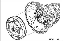
Remove the torque converter assy from the transmission assy.
|

|
1.Remove the bolt in order to remove the breather tube, breather hose, and breather plug
No. 1 from the transmission case.
SIZE: Bolt
M6 x 1.0 x 10 mm
2.Remove the O-ring from the breather tube.
3.Remove the O-ring from breather plug No. 1.
|
|
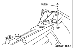
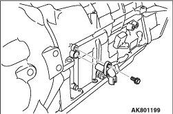
Remove the tube from the transmission case.
|
|
Remove the bolt to remove the speed sensor from the transmission case.
SIZE: Bolt
M6 x 1.0 x 14 mm
|
|
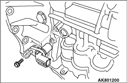
Remove the bolt to remove the speed sensor from the transmission case.
SIZE: Bolt
M6 x 1.0 x 14 mm
|

|
Remove the nut and spring washer in order to remove the transmission control shaft lever
LH from the manual valve lever shaft.
|

|
1.Remove the 2 elbows.
2.Remove the 2 O-rings from the elbows.
|
|
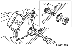
1.Using a screwdriver, pry off the washer.
2.Remove the nut to remove the washer from the inhibitor switch.
|
|
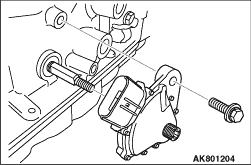
3.
| caution |
Be careful not to damage the inhibitor switch.
|
Remove the bolt (seal bolt) to remove the inhibitor switch from the transmission case.
SIZE: Bolt
M8 x 1.25 x 30 mm (Seal bolt)
|

|
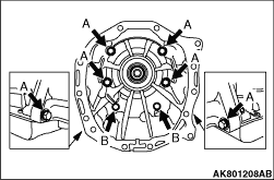
1.Remove the 10 bolts.
SIZE: Bolt
A: M10 x 1.5 x 35 mm
B: M10 x 1.5 x 35 mm (Seal bolt)
C: M12 x 1.75 x 38 mm (Seal bolt)
|

|
2.
| caution |
Be careful not to damage the fitting surface of the converter housing
and the transmission case.
|
Using a plastic hammer, tap the converter housing to remove it.
|
|
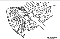
1.Remove the 8 bolts.
SIZE: Bolt
A: M10 x 1.5 x 40 mm (Seal bolt)
B: M10 x 1.5 x 50 mm (Seal bolt)
|
|
2.
| caution |
Be careful not to damage the fitting surface of the transmission case
RR adaptor and the transmission case.
|
Using a plastic hammer, tap the transmission case RR adaptor to remove it.
|

|
Remove the oil seal from the transmission case RR adaptor.
|
|
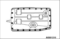
1.Remove the 20 bolts.
SIZE: Bolt
M6 x 1.0 x 14.5 mm
|
|
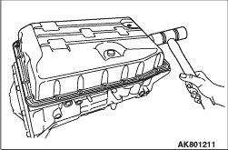
2.
| caution |
- Be careful not to damage the fitting surface of the transmission
case and the oil pan sub-assy.
- Be careful not to deform the oil pan sub-assy.
|
Using a plastic hammer, tap the oil pan sub-assy to remove it.
3.Remove the oil pan gasket.
|
|
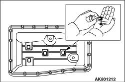
Remove the 4 oil cleaner magnets from the oil pan sub-assy.
| note |
Examine the chips and particles in the oil pan sub-assy and on the oil cleaner magnet
to determine what type of wear has occurred in the transmission.
Steel (magnetic) = bearing, gear and plate wear.
Brass (non-magnetic) = bushing wear.
|
|
|
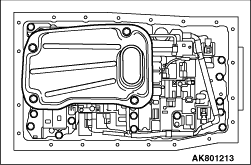
1.Remove the 4 bolts to remove the oil strainer assy from the valve body assy.
SIZE: Bolt
M6 x 1.0 x 12 mm
2.Remove the O-ring from the oil strainer assy.
|
|
SIZE: O-ring
Inner diameter (mm)
|
Thickness (mm)
|
31.00
|
2.72
|
|
|

|
1.Disconnect the 7 solenoid assy connectors from the solenoid assy.
2.Disconnect the harness from the valve body wire harness clamp.
|

|
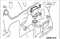
3.Remove the 2 bolts and 2 temperature sensor clamps and then pull out the temperature sensor
from the valve body assy.
SIZE: Bolt
A: M6 x 1.0 x 12 mm
B: M6 x 1.0 x 36 mm
|
|
4.Remove the bolt from the transmission case.
SIZE: Bolt
M6 x 1.0 x 16 mm
5.Remove the harness from the transmission case.
6.Remove the O-ring from the harness.
|
|
SIZE: O-ring
Inner diameter (mm)
|
Thickness (mm)
|
21.80
|
2.40
|
|
|
|
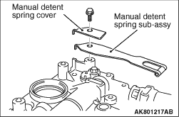
Remove the flange bolt to remove the manual detente spring and the manual detente spring
cover from the valve body assy.
SIZE: Flange bolt
M6 x 1.0 x 14 mm
|

|
1.Remove the 19 bolts from the transmission case as shown in the illustration.
SIZE: Bolt
A: M6 x 1.0 x 25 mm
B: M6 x 1.0 x 36 mm
2.
| caution |
Be careful not to drop the valve body assy.
|
Disconnect the manual valve link and remove the valve body assy.
|
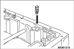
|
Remove the check valve sub-assy and the spring from the transmission case as shown in
the illustration.
|
|
SIZE: Spring
Free (mm)
|
Outer (mm)
|
38.55
|
4.861
|
|
|

|
Remove the 3 gaskets and the 3 gaskets from the transmission case as shown in the illustration.
|

|
1.
| caution |
Take care as the accumulator piston (Direct clutch, B3) may eject.
|
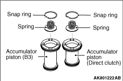
Apply compressed air into the oil passage as shown in the illustration and remove the
2 accumulator pistons and the 2 accumulator springs from the transmission case.
|
|
SIZE: Accumulator springs
Piston
|
Free
(mm)
|
Outer
(mm)
|
Color
|
Direct clutch
|
62.0
|
15.9
|
White
|
B3
|
70.5
|
19.7
|
Purple
|
|
|
|
2.
| caution |
Be careful not to damage the accumulator piston.
|
Using a screwdriver, remove the 2 snap rings from the 2 accumulator pistons.
3.Remove the 2 springs from the 2 accumulator pistons.
|
|
SIZE: Spring
Piston
|
Free
(mm)
|
Outer
(mm)
|
Color
|
direct clutch
|
14.16
|
11.3
|
-
|
B3
|
24.77
|
16.3
|
Purple
|
|
|

|
4.
| caution |
Be careful not to damage the accumulator piston.
|
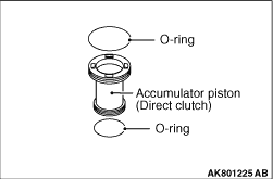
Using a screwdriver, remove the 4 O-rings from the 2 accumulator pistons.
|
|
SIZE: O-ring
Piston
|
Inner diameter
(mm)
|
Thickness
(mm)
|
Direct clutch
|
20.00
|
2.62
|
28.73
|
2.62
|
B3
|
23.55
|
2.62
|
34.29
|
2.62
|
|
|

|
1.
| caution |
Take care as the accumulator piston (Reverse clutch) may eject.
|
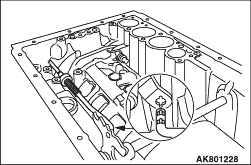
Apply compressed air into the oil passage as shown in the illustration and remove the
accumulator piston and the 2 accumulator springs from the transmission case.
|
|
SIZE: Accumulator springs
Piston
|
Free
(mm)
|
Outer
(mm)
|
Color
|
Reverse clutch
|
44.0
|
14.0
|
Yellow
|
73.35
|
19.9
|
Red
|
|
|
|
2.
| caution |
Be careful not to damage the accumulator piston.
|
Using a screwdriver, remove the 2 O-rings from the accumulator piston.
|
|
SIZE: O-ring
Inner diameter (mm)
|
Thickness (mm)
|
26.75
|
2.62
|
34.29
|
2.62
|
|
|

|
Remove the accumulator valve and the 2 springs from the transmission case.
|
|
SIZE: Spring
Piston
|
Free
(mm)
|
Outer
(mm)
|
Color
|
Accumulator
|
48.76
|
16.6
|
Light
green
|
30.40
|
11.4
|
Pink
|
|
|

|
Remove the 3 bolts to remove the parking lock pawl bracket.
SIZE: Bolt
M6 x 1.0 x 14 mm
|
|
Disconnect the parking lock rod sub-assy from the manual valve lever sub-assy.
|

|
1.
| caution |
Be careful not to apply too much force to the torsion spring.
|
Pull out the parking lock pawl shaft and the torsion spring.
2.Using a screwdriver, remove the snap ring from the parking lock pawl shaft.
3.Remove the parking lock pawl.
|

|
1.
| caution |
Be careful not to damage the manual valve lever sub-assy.
|
Using a hammer and a screwdriver, cut off the spacer to remove it.
|

|
2.Using a hammer and a pin punch, drive out the spring pin.
|

|
3.Pull the manual valve lever shaft out through the transmission case, and remove the manual
valve lever sub-assy.
|
|
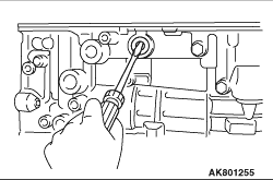
Using a screwdriver, remove the 2 oil seals.
|

|
1.Remove the 10 bolts from the transmission case.
SIZE: Bolt
M8 x 1.25 x 40 mm
|

|
2.
| caution |
Be careful not to drop the oil pump assy from the transmission case.
|
Using the special tool Oil pump puller (MD998212), remove the oil pump assy.
|

|
3.Remove the O-ring from the oil pump assy.
|
|
SIZE: O-ring
Inner diameter (mm)
|
Thickness (mm)
|
218.40
|
3.50
|
|
4.Remove the thrust needle roller bearing and the thrust bearing race No. 1 from the
oil pump assy.
|

|
1.
| caution |
- Be careful not to drop the forward clutch assy & direct clutch
assy.
- Be careful not to drop the one-way clutch No. 3.
|
Remove the forward clutch assy & direct clutch assy with the one-way clutch No.
3.
|

|
2.Remove the thrust bearing race and the thrust needle roller bearing from the forward clutch
assy & direct clutch assy.
|
|
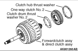
3.Remove the clutch hub thrust washer, one-way clutch No. 2 and the clutch drum thrust washer
No. 2 from the forward clutch assy & direct clutch assy.
|
|
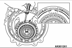
1.Using a screwdriver, remove the snap ring from the transmission case.
|

|
2.Remove the flange, 4 discs, 4 plates and cushion plate.
| note |
Check the number of disc. (Refer to TRANSMISSION INSPECTION-INSPECT BRAKE DISK SET No.
3 (B3)  ) )
|
|
|
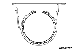
1.Remove the hole snap ring from the transmission case.
|
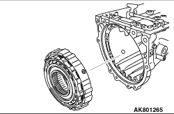
|
2.Remove the brake piston return spring sub-assy No. 3 & second brake piston & second
brake cylinder with the one-way clutch No. 1, planetary carrier thrust washer No. 1 and the
one-way clutch inner sub-assy.
|

|
3.Remove the one-way clutch inner race sub-assy and the planetary carrier thrust washer
No. 1
4.Remove the one-way clutch No. 1 from the brake piston return spring sub-assy No. 3 & second
brake piston & second brake cylinder.
|

|
Remove the FR planetary gear assy and the planetary carrier thrust washer No. 2.
|

|
1.Remove the FR planetary gear & FR planetary gear flange & middle planetary
ring gear.
2.Remove the thrust bearing race No. 3 and the thrust needle roller bearing from the
FR planetary gear & FR planetary gear flange & middle planetary ring gear.
|

|
Remove the flange, 4 discs and 4 plates.
| note |
Check the number of disc. (Refer to TRANSMISSION INSPECTION-INSPECT BRAKE DISK SET No.
1 (B1) )
|
|

|
1.Remove the middle planetary gear assy and planetary sun gear.
2.Remove the thrust needle roller bearing and the thrust bearing race No. 4 from the
middle planetary gear assy.
|

|
1.Set the special tool Adapter (MB992320) on the flange.
|

|
2.Using the special tools and a screwdriver, remove the hole snap ring from the transmission
case.
- Base (MB992317)
- Cylinder (MB992318)
- Center bolt (MB992319)
- Flange bolt (MB992322)
|
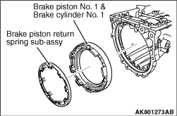
|
3.Remove the brake piston return spring sub-assy and the brake piston No. 1 & brake
cylinder No. 1.
|

|
1.Set the special tool Adapter (MB992321) on the brake piston return spring sub-assy.
|

|
2.Using the special tools and a screwdriver, remove the hole snap ring from the transmission
case.
- Base (MB992317)
- Cylinder (MB992318)
- Center bolt (MB992319)
- Flange bolt (MB992322)
|

|
4.Remove the 4 discs, 3 plates and flange.
| note |
Check the number of disc. (Refer to TRANSMISSION INSPECTION-INSPECT BRAKE DISK SET No.
2 (B2) )
|
|
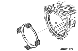
|
5.Remove the brake piston return spring sub-assy No. 2.
|
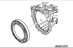
|
Remove the brake piston No. 2 and brake cylinder No. 2 from the transmission case.
|
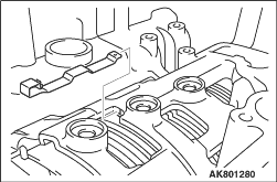
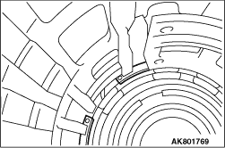
|
Remove the plate stopper spring from the transmission case.
|
|
1.Remove the hole snap ring from the transmission case.
|
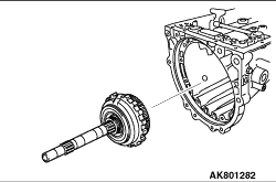
|
2.Remove the intermediate shaft with the one-way clutch inner race, one-way clutch No. 3,
RR planetary gear flange sub-assy & RR planetary gear, thrust bearing race No. 7, thrust needle
roller bearing and thrust bearing race No. 8 from the transmission case.
3.

Remove the one-way clutch inner race, one-way clutch No. 3, RR planetary gear flange sub-assy & RR
planetary gear, thrust bearing race No. 7, thrust needle roller bearing and the thrust bearing
race No. 8 from the intermediate shaft.
|
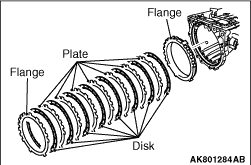
|
Remove the 2 flanges, 8 discs and 7 plates.
| note |
Check the number of disc. (Refer to TRANSMISSION INSPECTION-INSPECT BRAKE DISK SET No.
4 (B4) )
|
|

|
Remove the RR planetary gear assy with the thrust bearing race No. 9, thrust needle roller
with race bearing and thrust needle roller bearing.
|

|
1.Set the special tools as shown in the illustration, and compress the spring.
- Spring compressor body (MD998903)
- Retainer (MD998924)
2.
| caution |
Be careful not to expand the shaft snap ring too much.
|
Using special tools, remove the shaft snap ring.
|
|
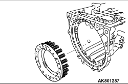
3.Remove the low/reverse brake return spring sub-assy.
|
|
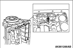
1.While pushing the inner brake piston No. 4 by hand, apply compressed air (392 kPa)
into the oil passage as shown in the illustration and remove the inner brake piston No. 4 from the
transmission case.
| note |
When applying compressed air, shut a oil passage of the transmission case as shown in
the illustration.
|
|
|
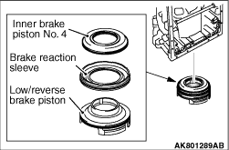
2.Remove the inner brake piston No. 4, brake reaction sleeve and reverse brake piston.
|

|
3.Remove the 2 O-rings from the inner brake piston No. 4.
|
|
SIZE: O-ring
Inner diameter (mm)
|
Thickness (mm)
|
67.35
|
2.62
|
116.40
|
2.62
|
|
|
|
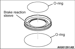
4.Remove the 2 O-rings from the brake reaction sleeve.
|
|
SIZE: O-ring
Inner diameter (mm)
|
Thickness (mm)
|
79.10
|
2.62
|
128.00
|
2.62
|
|
|

|
5.Remove the O-ring from the low/reverse brake piston.
|
|
SIZE: O-ring
Inner diameter (mm)
|
Thickness (mm)
|
131.60
|
2.62
|
|
|