|
|
Measure wheel alignment with alignment equipment on a level surface. The front suspension, steering system, wheels, and tyres should be serviced to normal condition before measuring wheel alignment.
|
|
|
Standard value:
At the centre of tyre tread: 0 - 5 mm
Toe-angle (per wheel): 0 ° 00’ - 0 ° 12’
|

|
1.Adjust the toe-in by undoing the clip and lock nut, and turning the left and right tie rod turnbuckles by the same amount (in opposite directions).
| note |
The toe will move out as the left turnbuckle is turned toward the front of the vehicle and the right turnbuckle is turned toward the rear of the vehicle.
|
2.Install the clip and tighten the lock nut to the specified torque.
Tightening torque: 93 ± 15 N·m
3.Confirm that the toe-in is at the standard value.
4.Use a turning radius gauge to check that the steering angle is at the standard value.
STEERING ANGLE
Standard value:
Inner wheel
|
Short wheelbase
|
36°49’ ± 1°30’
|
Long wheelbase
|
36°01’ ± 1°30’
|
Outer wheel (reference value)
|
Short wheelbase
|
32°06’
|
Long wheelbase
|
32°18’
|
|
|
Standard value:
Camber
|
0°00’ ± 0°30’*
|
Caster
|
Short wheelbase
|
3°39’ ± 1°00’*
|
Long wheelbase
|
3°31’ ± 1°00’*
|
Kingpin inclination
|
11°30’
|
| note |
*: Difference between right and left wheels must be less than 0° 30’
|
|

|
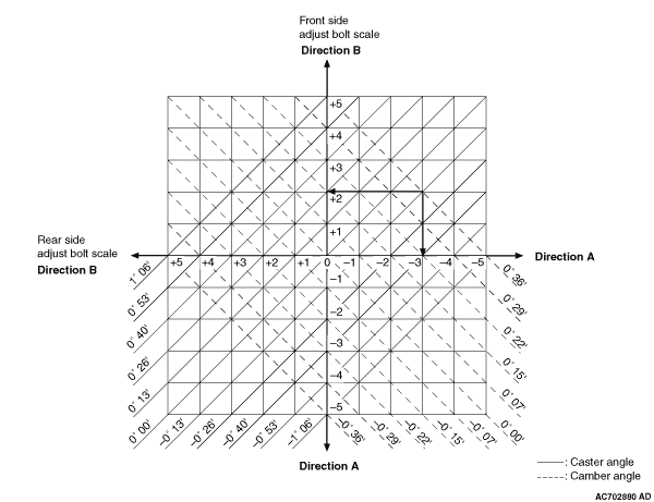
If the camber difference 0°36’ and the caster difference is -0°13’ by comparing the measurement value with the standard value, rotate the front adjusting cam by 2 graduations to the "A" direction and the rear adjusting cam by 3 graduations to the "B" direction.
| note |
Solid lines show caster, broken lines show camber.
|
|