DISASSEMBLY AND REASSEMBLY


Disassembly steps


1.
Filler cap


2.
Reservoir assembly


3.
Grommet
<<A>>
>>A<<
4.
Accumulator


5.
O-ring


6.
Spring


7.
Silencer tube


8.
Hose


9.
Tube


10.
Brake booster inner clamp


11.
Lead wire


12.
Bracket


13.
Pump motor assembly


14.
Clevis


15.
Boot
<<B>>

·
Holding the HBB
<<C>>

16.
Snap ring
<<C>>

17.
Brake booster inner plug
<<C>>

18.
Power piston assembly
<<C>>

19.
Master cylinder piston assembly


20.
Master cylinder and hydraulic unit assembly

DISASSEMBLY SERVICE POINTS


<<A>> ACCUMULATOR REMOVAL


caution When removing the accumulator, use a rag to prevent the brake fluid from dripping on the pump motor.

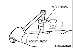
Use the special tool accumulator wrench (MB991926) shown in the figure to remove the accumulator.

<<B>> HOLDING THE HBB


Use the special tool valve spring compressor adapter (MB991620) and the spacer to hold the HBB as shown.

<<C>> SNAP RING, BRAKE BOOSTER INNER PLUG, POWER PISTON ASSEMBLY AND MASTER CYLINDER PISTON ASSEMBLY REMOVAL


  1. Push in the push rod of the power piston assembly, and then use a small flat-tipped screwdriver to remove the snap ring.
    note If the snap ring can not be released easily, use a pin to push the snap ring out of the cylinder body hole (A).
  2. caution Do not damage the cylinder wall.
    Withdraw the power piston assembly and the master cylinder piston assembly squarely from the cylinder body.

REASSEMBLY SERVICE POINT


>>A<< ACCUMULATOR INSTALL


Use the special tool accumulator wrench (MB991926) to install the accumulator.

ACCUMULATOR DISPOSAL


Refer to .