Pre-removal Operation
- Battery, Battery Box Removal (Refer to GROUP 54A -
Battery
 ). ).
- Radiator Condenser Tank Removal (Refer to GROUP 14 -
Radiator ) <3200>.
- Suction Control Valve Connector and Fuel Temperature Sensor Harness Connector Removal (Refer
to GROUP 13B -
Supply Pump ).
- Camshaft Position Sensor Removal (Refer to GROUP 13B -
Camshaft Position
Sensor ).
- Vacuum Hose Removal (Refer to GROUP 15 -
Intake Manifold <3800>, <3200 >) .
- A/C Drive Belt, A/C Compressor Connector Clamp, A/C Compressor Assembly and A/C
Pipe Clamp Bolt Removal (Refer to GROUP 55 -
Compressor Assembly <3800>, <3200>).
- Power Steering Fluid Draining (Refer to ).
|
Post-installation Operation
- Power Steering Fluid Supplying and Bleeding (Refer to ).
- A/C Pipe Clamp Bolt, A/C Compressor Assembly, A/C Compressor Connector Clamp and
A/C Drive Belt Installation (Refer to GROUP 55 -
Compressor Assembly <3800>, <3200>).
- Vacuum Hose Installation (Refer to GROUP 15 -
Intake Manifold <3800>, <3200>).
- Camshaft Position Sensor Installation (Refer to GROUP 13B -
Camshaft Position
Sensor ).
- Suction Control Valve Connector and Fuel Temperature Sensor Harness Connector Installation (Refer
to GROUP 13B -
Supply Pump ).
- Radiator Condenser Tank Installation (Refer to GROUP 14 -
Radiator ) <3200>.
- Battery, Battery Box Installation (Refer to GROUP 54A -
Battery ).
|
|
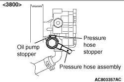
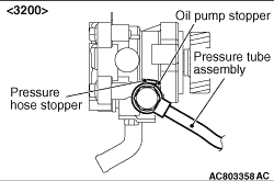
Place the pressure hose stopper to touch the power steering pump stopper, and install
the pressure hose.
|
|
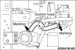
Install the suction hose so that the marking is positioned upward.
|

