|
|
If the reversing sensor OFF indicator illuminate when the ignition switch is turned to the "ON" position, the power supply system is normal. The wiring harness, connectors, corner sensor-ECU may be defective.
|
|
|
- Damaged harness wires and connectors
- Malfunction of corner sensor-ECU
- Malfunction of ignition switch (IG2)
|
|
|
Q.
Is the check result normal?
|
|
|
 Repair the defective connector. Repair the defective connector.
|
|
|
|
|
|
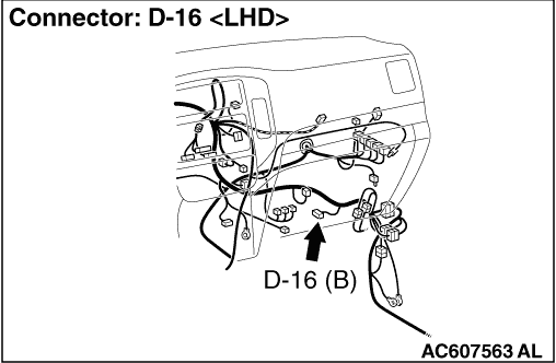
(1)Disconnect corner sensor-ECU connector D-16, and measure at the wiring harness side.
|
|
|
(2)Turn the ignition switch to "ON" position.
|
|
|
(3)Measure the voltage between terminal 11 and earth.
OK: System voltage
|
|
|
Q.
Is the check result normal?
|
|
|
- Check the power supply line for open circuit and short circuit.
|
|
|
Q.
Is the check result normal?
|
|
|
Repair the wiring harness.
|
|
|
|
|
|
(1)Disconnect corner sensor-ECU connector D-16, and measure at the wiring harness side.
|
|
|
(2)Measure the resistance between terminal 20 and earth.
OK: Continuity exists (2 Ω or less)
|
|
|
Q.
Is the check result normal?
|
|
|
- Check the earth wires for open circuit.
|
|
|
Q.
Is the check result normal?
|
|
|
Repair the wiring harness.
|
|
|
|
|
|
After replacing the corner sensor-ECU, inspect the reversing sensor system for normal operation.
|
|
|
Q.
Is the check result normal?
|
|
|
 The procedure is complete. The procedure is complete.
|
|
|
|
|
|
Replace the ignition switch.
|
|
|
|