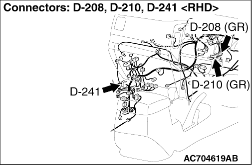
|
|
Q.
Is D-210 multivision display connector in good condition?
|
|
|
 Repair or replace the damaged component(s). Repair or replace the damaged component(s).
|
|
|
|
|
|
(1)Disconnect multivision display connector D-210 and measure the resistance available at the wiring harness side of the connector.
|
|
|
(2)Measure the resistance between D-210 multivision display connector terminal 9 and earth.
OK: The resistance should be 2 ohms or less
|
|
|
Q.
Is the measured resistance 2 ohms or less?
|
|
|
- Check the earth wires for open circuit.
|
|
|
Q.
Is the check result normal?
|
|
|
 The trouble can be an intermittent malfunction (Refer to GROUP 00, How to use Troubleshooting/inspection Service Points, How to Cope with Intermittent Malfunction The trouble can be an intermittent malfunction (Refer to GROUP 00, How to use Troubleshooting/inspection Service Points, How to Cope with Intermittent Malfunction  ). ).
|
|
|
|
|
|
Repair the wiring harness.
|
|
|
|
|
|
(1)Disconnect multivision display connector D-208 and measure the resistance available at the wiring harness side of the connector.
|
|
|
(2)Measure the resistance between D-208 multivision display connector terminal 25 and earth.
OK: The resistance should be 2 ohms or less
|
|
|
Q.
Is the measured resistance 2 ohms or less?
|
|
|
- Check the earth wires for open circuit.
|
|
|
Q.
Is the check result normal?
|
|
|
The trouble can be an intermittent malfunction (Refer to GROUP 00, How to use Troubleshooting/inspection Service Points, How to Cope with Intermittent Malfunction ).
|
|
|
|
|
|
Repair the wiring harness.
|
|
|
|
|
|
(1)Disconnect the connector, and measure at the wiring harness-side connector.
|
|
|
(2)Voltage between D-210 multivision display terminal No.17 and the body earth
OK: System voltage
|
|
|
Q.
Is the check result normal?
|
|
|
- Check the power supply lines (battery supply) for open circuit and short circuit.
|
|
|
Q.
Is the check result normal?
|
|
|
Repair the wiring harness.
|
|
|
|
|
|
(1)Disconnect the connector, and measure at the wiring harness-side connector.
|
|
|
(2)Turn the ignition switch to the ACC position.
|
|
|
(3)Voltage between D-210 multivision display terminal No.14 and the body earth
OK: System voltage
|
|
|
Q.
Is the check result normal?
|
|
|
- Check the power supply lines (battery supply) for open circuit and short circuit.
|
|
|
Q.
Is the check result normal?
|
|
|
Refer to Inspection procedure 2 "Malfunction of the ignition switch power supply system ."
|
|
|
|
|
|
Repair the wiring harness.
|
|
|
|
|
|
(1)Disconnect the connector, and measure at the wiring harness-side connector.
|
|
|
(2)Voltage between D-208 multivision display terminal No.21 and the body earth
OK: System voltage
|
|
|
Q.
Is the check result normal?
|
|
|
- Check the power supply lines (battery supply) for open circuit and short circuit.
|
|
|
Q.
Is the check result normal?
|
|
|
The trouble can be an intermittent malfunction (Refer to GROUP 00, How to use Troubleshooting/inspection Service Points, How to Cope with Intermittent Malfunction ).
|
|
|
|
|
|
Repair the wiring harness.
|
|
|
|
|
|
Check if the multivision display power is turned ON.
|
|
|
Q.
Is the check result normal?
|
|
|
The trouble can be an intermittent malfunction (Refer to GROUP 00 - How to use Troubleshooting/inspection Service Points - How to Cope with Intermittent Malfunction ).
|
|
|
|
|
|
Replace the multivision display.
|
|
|
|