|
|
Q.
Is the check result normal?
|
|
|
 Repair the defective connector. Repair the defective connector.
|
|
|
|
|
|
(1)Disconnect the connector, and measure at the wiring harness side.
|
|
|
(2)Turn the Ignition switch to the "LOCK" (OFF) position.
|
|
|
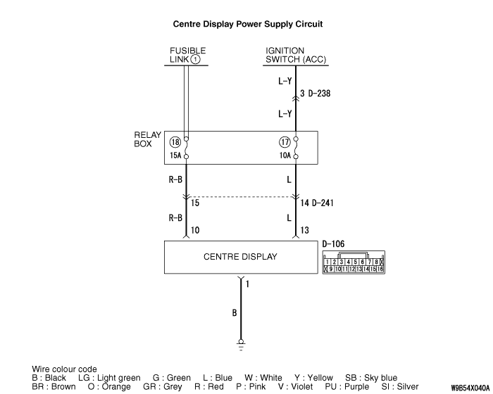
(3)Voltage between D-106 centre display unit connector terminal No.10 and body earth
OK: System voltage
|
|
|
Q.
Is the check result normal?
|
|
|
- Check the battery power supply open circuit and short circuit.
|
|
|
Q.
Is the check result normal?
|
|
|
Repair the wiring harness.
|
|
|
|
|
|
(1)Disconnect the connector, and measure at the wiring harness side.
|
|
|
(2)Turn the ignition switch to the "ACC" position.
|
|
|
(3)Voltage between D-106 centre display unit connector terminal No.13 and body earth
OK: System voltage
|
|
|
Q.
Is the check result normal?
|
|
|
- Check the ACC power supply open circuit and short circuit.
|
|
|
Q.
Is the check result normal?
|
|
|
 Refer to Inspection procedure 2 "Malfunction of the ignition switch power supply system Refer to Inspection procedure 2 "Malfunction of the ignition switch power supply system  ." ."
|
|
|
|
|
|
Repair the wiring harness.
|
|
|
|
|
|
(1)Disconnect the connector, and measure at the wiring harness side.
|
|
|
(2)Resistance between D-106 centre display unit connector terminal No.1 and body earth
OK: Continuity exists (2 Ω
or less)
|
|
|
Q.
Is the check result normal?
|
|
|
- Check the earth wires for open circuit.
|
|
|
Q.
Is the check result normal?
|
|
|
Repair the wiring harness.
|
|
|
|
|
|
Check that the centre display correctly when the centre display unit is replaced temporarily.
|
|
|
Q.
Is the check result normal?
|
|
|
Replace the centre display unit.
|
|
|
|
|
|
Check that the centre display unit correctly.
|
|
|
Q.
Is the check result normal?
|
|
|
The procedure is complete.
|
|
|
|