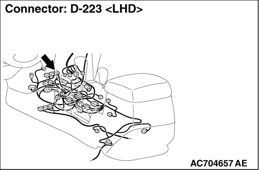
|
|
(1)Remove the ASTC-ECU, and measure at the equipment side.
|
|
|
(2)Resistance at D-223 ASTC-ECU connector terminal Nos.83 and 84
OK: 120 ± 20 Ω
|
|
|
Q.
Is the check result normal?
|
|
|
 <Within 120 ± 20 Ω> Go to Step 2. <Within 120 ± 20 Ω> Go to Step 2.
|
|
|
|
|
|
 <Not within 120 ± 20 Ω> Replace the ASTC-ECU. <Not within 120 ± 20 Ω> Replace the ASTC-ECU.
|
|
|
|
|
|
(1)Remove the combination meter, and measure at the equipment side.
|
|
|
(2)Resistance between D-04 combination meter connector terminal Nos.23 and 24
OK: 120 ± 20 Ω
| caution |
Strictly observe the specified wiring harness repair procedure. For details refer to  . .
|
|
|
|
Q.
Is the check result normal?
|
|
|
<Within 120 ± 20 Ω> Repair the wiring harness between the ASTC-ECU connector and the combination meter.
|
|
|
|
|
|
<Not within 120 ± 20 Ω> Replace the combination meter.
|
|
|
|