|
|
When checking the joint connector, ensure that its wiring harness side and its short pins are not damaged.
|
|
|
Q.
Is the check result normal?
|
|
|
 Repair the defective connector. Replace the joint connector as necessary. Repair the defective connector. Replace the joint connector as necessary.
|
|
|
|
|
|
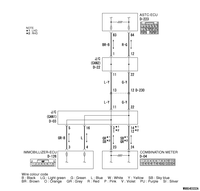
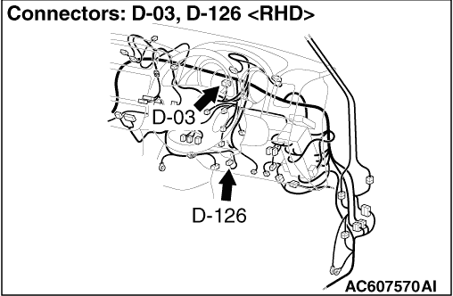
(1)Disconnect joint connector (CAN1) and the immobilizer-ECU connector, and measure at the wiring harness side.
|
|
|
(2)Turn the ignition switch to the LOCK (OFF) position.
|
|
|
(3)
| caution |
When measuring the resistance, disconnect the negative battery terminal. For details refer to  . .
|
Ensure that the negative battery terminal is disconnected.
|
|
|
(4)Continuity between D-03 joint connector (CAN1) terminal No.5 and D-126 immobilizer-ECU connector terminal No.3
OK: Continuity (2 Ω or less)
|
|
|
(5)Continuity between D-03 joint connector (CAN1) terminal No.16 and D-126 immobilizer-ECU connector terminal No.4
OK: Continuity (2 Ω or less)
| caution |
Strictly observe the specified wiring harness repair procedure. For details refer to .
|
|
|
|
Q.
Is the check result normal?
|
|
|
 <All the resistances measure 2 Ω or less> Power supply to the immobilizer-ECU may be suspected. Diagnose the immobilizer-ECU. Refer to GROUP 54A, Immobilizer system - Symptom procedure . <All the resistances measure 2 Ω or less> Power supply to the immobilizer-ECU may be suspected. Diagnose the immobilizer-ECU. Refer to GROUP 54A, Immobilizer system - Symptom procedure .
|
|
|
|
|
|
NO : <Either or all of the resistances measure more than 2 Ω> Repair the wiring harness between joint connector (CAN1) and the immobilizer-ECU connector.
|
|
|
|