|
|
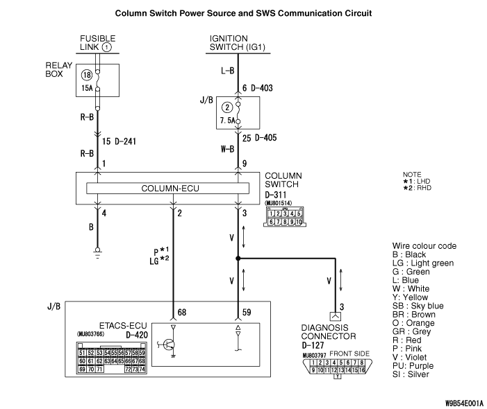
The power supply circuit to the column switch (column-ECU) may be defective. If the wiring harness of the battery power supply circuit for the ECU (column switch terminal No.1) is defective, also check the power supply circuit to the ignition switch (IG1) (column switch terminal No.9) and repair if necessary.
|
|
|
- Malfunction of the ETACS-ECU
- Malfunction of the lighting switch
- Damaged harness wires and connectors
|
|
|
Check that the power supply and earth lines to the ETACS-ECU and the SWS communication lines are normal.
|
|
|
OK: "OK" is displayed on the "ETACS ECU" menu.
|
|
|
Q.
Is the check result normal?
|
|
|
 Refer to Inspection Procedure 2 "Communication with the ETACS-ECU is not possible Refer to Inspection Procedure 2 "Communication with the ETACS-ECU is not possible  ." ."
|
|
|
|
|
|
Q.
Is the check result normal?
|
|
|
Repair the defective connector.
|
|
|
|
|
|
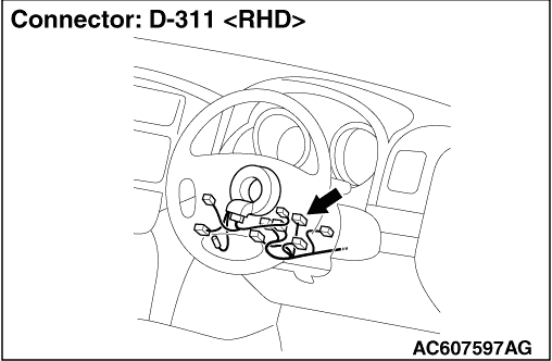
(1)Remove the column switch connector, and measure at the wiring harness side.
|
|
|
(2)Voltage between D-311 column switch connector terminal No.1 and body earth
OK: System voltage
|
|
|
Q.
Is the check result normal?
|
|
|
- Check the power supply line for open circuit.
|
|
|
Q.
Is the check result normal?
|
|
|
 The trouble can be an intermittent malfunction (Refer to GROUP 00 - How to use troubleshooting/Inspection Service Points ). The trouble can be an intermittent malfunction (Refer to GROUP 00 - How to use troubleshooting/Inspection Service Points ).
|
|
|
|
|
|
Repair the wiring harness.
|
|
|
|
|
|
(1)Remove the column switch connector, and measure at the wiring harness side.
|
|
|
(3)Voltage between D-311 column switch connector terminal No.9 and body earth
OK: System voltage
|
|
|
Q.
Is the check result normal?
|
|
|
- Check the power supply line for open circuit.
|
|
|
Q.
Is the check result normal?
|
|
|
The trouble can be an intermittent malfunction (Refer to GROUP 00 - How to use troubleshooting/Inspection Service Points ).
|
|
|
|
|
|
Repair the wiring harness.
|
|
|
|
|
|
(1)Remove the column switch, and measure at the wiring harness side.
|
|
|
(2)Resistance between D-311 column switch connector terminal No.4 and body earth
OK: Continuity exists (2 Ω or less)
|
|
|
Q.
Is the check result normal?
|
|
|
- Check the earth wires for open circuit.
|
|
|
Q.
Is the check result normal?
|
|
|
The trouble can be an intermittent malfunction (Refer to GROUP 00 - How to use troubleshooting/Inspection Service Points ).
|
|
|
|
|
|
Repair the wiring harness.
|
|
|
|
|
|
Q.
Is the check result normal?
|
|
|
Repair the defective connector.
|
|
|
|
|
|
- Check the communication lines for open and short circuit.
|
|
|
Q.
Is the check result normal?
|
|
|
Repair the wiring harness.
|
|
|
|
|
|
OK: "OK" is displayed on the "COLUMN ECU" menu.
|
|
|
Q.
Is the check result normal?
|
|
|
Replace the lighting switch.
|
|
|
|
|
|
Check that the ETACS-ECU communicates with the column switch.
|
|
|
Q.
Is the check result normal?
|
|
|
The trouble can be an intermittent malfunction (Refer to GROUP 00 - How to use troubleshooting/Inspection Service Points ).
|
|
|
|