Anticipation by odometer
|
Calculating travel distance through vehicle speed sensor, engine-ECU
anticipates that PM accumulates more than criteria when specified travel distance is accumulated
from previous DPF regeneration.
|
Anticipation by difference in pressure
|
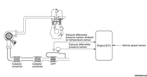
Detecting difference in pressure before and after DPF through exhaust
differential pressure sensor, engine-ECU anticipates amount of accumulated PM, adding compensation
through exhaust differential pressure sensor ambient air temperature sensor.
|
Anticipation by quantity survey
|
Engine-ECU anticipates amount of exhaust PM based on operation conditions,
which multiplying allows engine-ECU to anticipate amount of accumulated PM.
|

|
Detecting that the PM accumulates more than standard in the DPF, the engine-ECU sends
the request signal to the combination meter in order to light the DPF lamp through the CAN.
This allows the driver to be encouraged to drive with operating conditions effective to the
automatic regeneration. When the vehicle continuously runs with the DPF lamp lighted and without
the DPF regeneration, the engine warning lamp is lighted and the DPF lamp starts to blink. This
shows that the amount of accumulated PM exceeds the specified amount. When the DPF automatic
regeneration is performed under this condition, the DPF temperature is extremely higher depending on
the operation and the DPF might be damaged. This causes the DPF automatic regeneration not to
be performed when the DPF lamp blinks. Therefore, the DPF regeneration needs to be forcibly
performed.
The engine-ECU assumes the increase and decrease in the engine oil level, based on the
driving conditions. When the assumed engine oil level increase more than specified value, the
DPF lamp blinks. This allows the driver to be informed that the engine oil level is abnormal.
|
|
|
The DPF regeneration has the forcible regeneration by M.U.T.-III and the automatic regeneration
automatically performed while the vehicle is running. The automatic regeneration is performed
under the following conditions:
|
|
|
- Engine: after warm-up
- Transmission: D range
- Vehicle speed: 40 km/h or more
- Amount of accumulated PM exceeds specified value.
|
|
|
Performing the optimum engine control for the DPF regeneration, the engine-ECU increases
the temperature up to the point at which the DPF regeneration can be carried out, and then keeps
the temperature to burn the PM.
|
|
|
Performing rising temperature control having two steps, the engine-ECU increases the temperature
up to the point at which the DPF regeneration can be carried out. At the first, the engine-ECU
drives the variable geometry control solenoid valve and the throttle valve control servo and
then performs the fuel injection with the optimum injection pattern, decreasing the intake air
amount. This allows the high temperature exhaust gas to discharge as well as allows the catalyst
in the front of the DPF to be heated to about 200°C, resulting in the catalyst activated,
which is monitored by the No. 1 exhaust gas temperature sensor.
|
|
|
After the catalyst is activated, the engine-ECU performs the fuel injection called "post-injection"
having more retarded timing than the usual timing. This allows the oxygen to react, in the catalyst,
with the HC contained in the exhaust gas as well as allows the exhaust gas temperature to reach
about 600°C at which the DPF regeneration can be carried out, which is monitored by
the No. 2 exhaust gas temperature sensor (catalyst temperature).
|
|
|
When starting to perform the DPF regeneration, the engine-ECU carries out the feedback
control so that the temperature in the DPF can stabilize at about 600°C through the
output signal of the No.3 exhaust gas temperature sensor (DPF temperature). Controlling the
injection amount of the post-injection and the intake air amount regulates the temperature in the
DPF.
|
|
|
When being out of the regeneration condition during the automatic regeneration, the DPF
regeneration stops. If, however, satisfying the regeneration condition right after that, the
DPF regeneration is continuously carried out.
|

|
The No. 1 exhaust gas temperature sensor is installed to the center of the catalyst, the
No. 2 exhaust gas temperature sensor (catalyst temperature) is installed to the downstream area
of the catalyst and the No. 3 exhaust gas temperature sensor (DPF temperature) is installed
to the downstream area of the DPF. Each sensor detects the temperature in the each area through
the change in the thermistor resistance and outputs the voltage to the engine-ECU in accordance
with the temperature. The engine-ECU performs the DPF regeneration control through this output
voltage. The sensor characteristics are as shown in the charts.
|

|
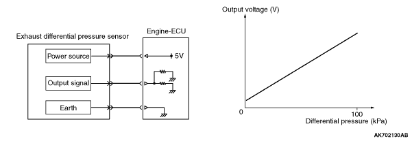
The exhaust differential pressure sensor is installed around the upper area of the DPF.
Using the piezo resistive semiconductor, the exhaust differential pressure sensor outputs the
voltage to the engine-ECU in accordance with the difference in the voltage between the DPF upstream
area and the DPF downstream area. The engine-ECU anticipates the amount of PM accumulated in
the DPF through this output voltage. The sensor characteristics are as shown in the charts.
|

|
The exhaust differential pressure sensor ambient air temperature sensor is around the
upper area of the DPF. The exhaust differential pressure sensor ambient air temperature sensor
detects the exhaust differential pressure sensor ambient air temperature through the change
in the thermistor resistance and outputs the voltage to the engine-ECU in accordance with the
exhaust differential pressure sensor ambient air temperature. The engine-ECU uses this output voltage
for the compensation in calculating the amount of accumulated PM through the exhaust differential
pressure. The sensor characteristics are as shown in the charts.
|