|
|
Measure backlash between gears, pair by pair, at three or more point. If the reading exceeds the specified standard value, replace defective part.
|
|
|
Standard value:
Balance shaft gear RH and oil pump gear
0.040 - 0.192 mm
Oil pump gear and crankshaft gear
0.098 - 0.158 mm
Crankshaft gear and idler gear
0.082 - 0.142 mm
Idler gear LH and idler gear
0.040 - 0.196 mm
Idler gear LH and balance shaft gear LH
0.040 - 0.222 mm
Idler gear and idler B gear
0.096 - 0.156 mm
|
|
|
If the reading exceeds the specified standard value, replace defective part.
|
|
|
Standard value:
Balance shaft LH, RH
0.09 - 0.24 mm
Idler gear and sprocket assembly
0.05 - 0.20 mm
Idler gear LH assembly
0.05 - 0.20 mm
|
|
|
Limit:
Balance shaft LH, RH
0.3 mm
Idler gear and sprocket assembly
0.3 mm
Idler gear LH assembly
0.3 mm
|
|
|
1.Using the bar, hold the balancer shaft drive gear RH.
|
|
|
2.Remove the balancer shaft drive gear RH bolt.
|
|
|
1.Using the bar, hold the balancer shaft drive gear LH.
|
|
|
2.Remove the balancer shaft drive gear LH bolt.
|

|
Using the special tool Idler sprocket bush puller (MH062462), remove the idler gear bush.
|
|
| caution |
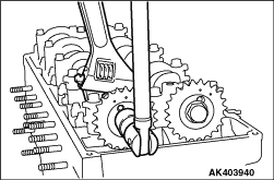
- When removing the bolt be sure to lock the camshaft by holding the hexagonal part A with a proper wrench. Do not use the timing chain b for the locking.
- The bolt is inversely threaded. The arrow mark on its head B indicates its turning direction when tightened. To remove, turn the bolt in the reverse direction.
- The camshaft sprocket a and timing chain b must be meshed in a fixed position. Do not remove the timing chain from the camshaft sprockets unless absolutely necessary.
|
|

|
| caution |
The bolt is inversely threaded. The arrow mark on its head B indicates its tuning direction when tightened.
|
|
|
Using the special tool Idler sprocket bush puller (MH062462), press-fit the idler gear bushing into the idler gear from the side showing the match marks "0."
|

|
Install the idler gear and sprocket assembly onto the idler shaft while aligning the mark "1" with that on the crankshaft gear.
|

|
1.Assemble the parts shown in the illustration to the balance shaft LH.
Be sure that the washer and thrust spacer face in correct direction as shown. Install the balance shaft LH with the side showing the match mark "0" outward.
|

|
2.Insert the completed balance shaft LH assembly into the crankcase assembly and set it in position with the dowel pin on the crankcase assembly.
| caution |
- Do not rotate the balance shaft LH assembly during insertion into the crankcase assembly.
This may cause the O-ring to be slipped out of place.
- Insert the balance shaft LH assembly using care not to damage the inner surface of the rear bearing in the crankcase.
|
|

|
Install the idler gear LH assembly onto the idler shaft. At this time, be sure to align the match marks "3" and "0" on the idler gear with the corresponding match marks on the idler gear and sprocket assembly and the balance shaft gear LH.
|

|
1.Assemble the parts shown in the illustration to the balance shaft RH.
Be sure to install the washer and thrust spacer in the direction shown in the illustration, and install the balance shaft gear RH with its mating mark "0" aligned with the mating mark "6" on the oil pump gear.
2.Insert the completed balance shaft RH assembly into the crankcase assembly while aligning the mating marks "5" on the oil pump gear and the crankshaft gear, and set the shaft assembly in position with the dowel pin on the crankcase assembly.
| caution |
Insert the balance shaft RH assembly using care not to damage the inner surface of the rear bearing in the crankcase.
|
3.After the timing gear are installed in position, check that all the rotary parts smoothly rotate.
|

