|
|
Q.
Are the check results normal?
|
|
|
 Repair or replace the connector. Repair or replace the connector.
|
|
|
|
|
|
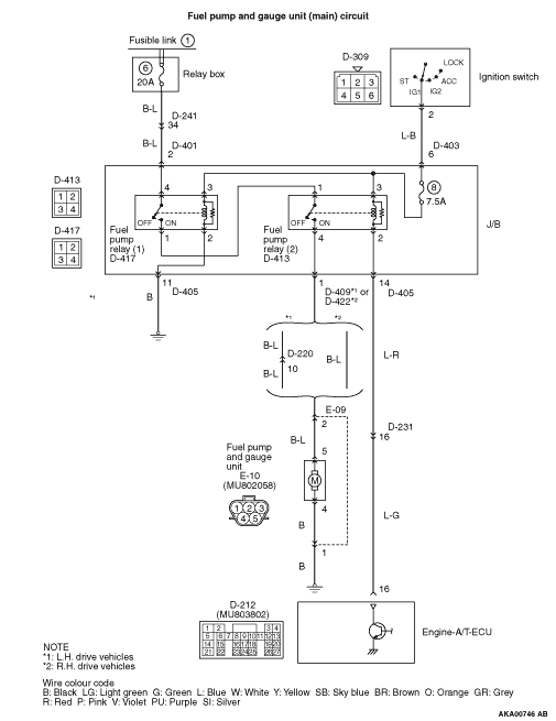
- Fuel pump relay, continuity check (Refer to
 ). ).
|
|
|
Q.
Is the check result normal?
|
|
|
Replace the fuel pump relay.
|
|
|
|
|
|
- Remove relay, and measure at junction block side.
- Resistance between terminal No. 2 and earth.
|
|
|
OK: Continuity (2 Ω or less)
|
|
|
Q.
Is the check result normal?
|
|
|
Check intermediate connector D-405, and repair
if necessary. If intermediate connector is normal, check and repair harness between D-417 (terminal
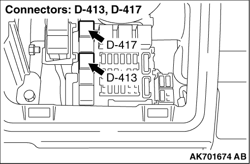
No. 2) fuel pump relay (1) connector and body earth.
- Check earthing line for open circuit and damage.
|
|
|
|
|
|
- Remove relay, and measure at junction block side.
- Ignition switch: ON
- Voltage between terminal No. 3 and earth.
|
|
|
Q.
Is the check result normal?
|
|
|
Q.
Is the check result normal?
|
|
|

Check intermediate connector D-403, and repair
if necessary. If intermediate connector is normal, check and repair harness between D-417 (terminal
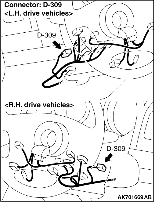
No. 3) fuel pump relay (1) connector and D-309 (terminal No. 2) ignition switch connector.
- Check power supply line for open circuit and damage.
|
|
|
|
|
|
Repair or replace the connector.
|
|
|
|
|
|
- Remove relay, and measure at junction block side.
- Voltage between terminal No. 4 and earth.
|
|
|
Q.
Is the check result normal?
|
|
|
Check intermediate connectors D-241 and D-401, and
repair if necessary. If intermediate connectors are normal, check and repair harness between
D-417 (terminal No. 4) fuel pump relay (1) connector and battery.
- Check power supply line for open/short circuit.
|
|
|
|
|
|
- Remove relay, and measure at junction block side.
- Ignition switch: ON
- Voltage between terminal No. 3 and earth.
|
|
|
Q.
Is the check result normal?
|
|
|
Q.
Is the check result normal?
|
|
|
Check intermediate connector D-403, and repair
if necessary. If intermediate connector is normal, check and repair harness between D-309 (terminal
No. 2) ignition switch connector and D-413 (terminal No. 3) fuel pump relay (2) connector.
- Check power supply line for open circuit.
|
|
|
|
|
|
Repair or replace the connector.
|
|
|
|
|
|
Q.
Is the check result normal?
|
|
|
Repair or replace the connector.
|
|
|
|
|
|
- Disconnect connector, and measure at harness side.
- Ignition switch: ON
- Voltage between terminal No. 16 and earth.
|
|
|
Q.
Is the check result normal?
|
|
|
Check intermediate connectors D-231 and D-405, and
repair if necessary. If intermediate connectors are normal, check and repair harness between
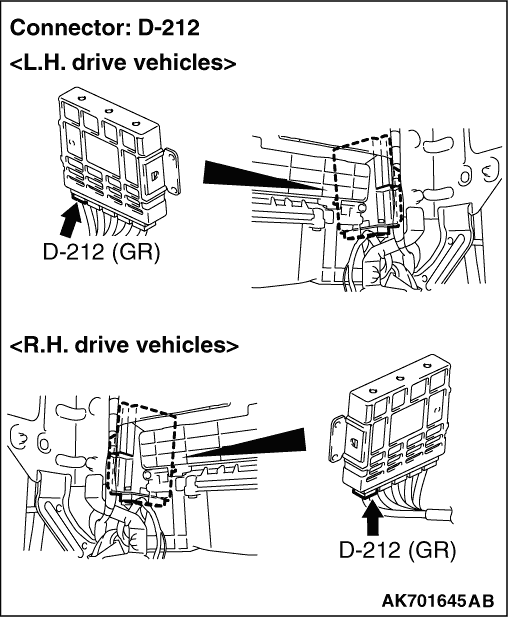
D-413 (terminal No. 2) fuel pump relay (2) connector and D-212 (terminal No. 16) engine-A/T-ECU connector.
- Check earthing line for open/short circuit.
|
|
|
|
|
|
Q.
Is the check result normal?
|
|
|
Repair or replace the connector.
|
|
|
|
|
|
- Disconnect connector, and measure at harness side.
- Ignition switch: ON
- Using a jumper wire, connect D-212 (terminal No. 16) engine-A/T-ECU connector and
earth.
- Voltage between terminal No. 5 and earth.
|
|
|
Q.
Is the check result normal?
|
|
|
- Check power supply line for open/short circuit.
|
|
|
Q.
Is the check result normal?
|
|
|
Repair the damaged harness wire.
|
|
|
|
|
|
- Check output line for open/short circuit and damage.
|
|
|
Q.
Is the check result normal?
|
|
|
Replace the engine-A/T-ECU.
|
|
|
|
|
|
Repair the damaged harness wire.
|
|
|
|
|
|
- Disconnect connector, and measure at harness side.
- Resistance between terminal No. 4 and earth.
|
|
|
OK: Continuity (2 Ω or less)
|
|
|
Q.
Is the check result normal?
|
|
|
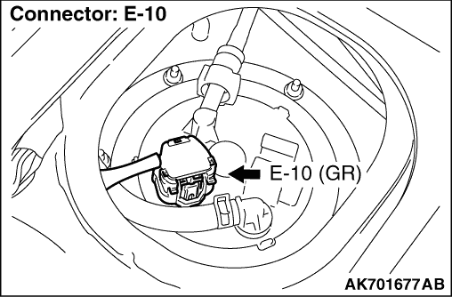
Check intermediate connector E-09, and repair
if necessary. If intermediate connector is normal, check and repair harness between E-10 (terminal No.
4) fuel pump connector and body earth.
- Check earthing line for open circuit and damage.
|
|
|
|
|
|
Q.
Is the check result normal?
|
|
|
Repair or replace the connector.
|
|
|
|
|
|
- Check power supply line for damage.
|
|
|
Q.
Is the check result normal?
|
|
|
Repair the damaged harness wire.
|
|
|
|
|
|
- Check power supply line for damage.
|
|
|
Q.
Is the check result normal?
|
|
|
Repair the damaged harness wire.
|
|
|
|
|
|
- Check power supply line for damage.
|
|
|
Q.
Is the check result normal?
|
|
|
Repair the damaged harness wire.
|
|
|
|
|
|
- Check power supply line for damage.
|
|
|
Q.
Is the check result normal?
|
|
|
Repair the damaged harness wire.
|
|
|
|
|
|
- Check power supply line for damage.
|
|
|
Q.
Is the check result normal?
|
|
|
Repair the damaged harness wire.
|
|
|
|
|
|
- Check earthing line for damage.
|
|
|
Q.
Is the check result normal?
|
|
|
Repair the damaged harness wire.
|
|
|
|