|
|
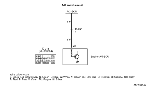
- Measure engine-A/T-ECU terminal voltage.
- Engine: Idling
|
|
|
- A/C set temperature:
Maximum Cool when temperature in cabin is 25°C
or more
Maximum Hot when temperature in cabin is 25°C or less
- Voltage between terminal No. 69 and earth.
|
|
|
OK:
System voltage (when A/C is ON)
0.5 V or less (when A/C is OFF)
|
|
|
Q.
Is the check result normal?
|
|
|
 Check A/C system (Refer to GROUP 55 - Troubleshooting - Check
Chart for Trouble Symptoms Check A/C system (Refer to GROUP 55 - Troubleshooting - Check
Chart for Trouble Symptoms  ). ).
|
|
|
|
|
|
Q.
Is the check result normal?
|
|
|
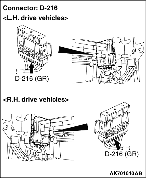
Repair or replace the connector.
|
|
|
|
|
|
- Engine: Idling
- A/C set temperature:
Maximum Cool when temperature in cabin is 25°C or
more
Maximum Hot when temperature in cabin is 25°C or less
|
|
|
OK:
ON (when A/C is ON)
OFF (when A/C is OFF)
|
|
|
Q.
Is the check result normal?
|
|
|
 Intermittent malfunction (Refer to GROUP 00 - How to Use Troubleshooting/Inspection
Service Points - How to Cope with Intermittent Malfunctions ). Intermittent malfunction (Refer to GROUP 00 - How to Use Troubleshooting/Inspection
Service Points - How to Cope with Intermittent Malfunctions ).
|
|
|
|
|
|
Replace the engine-A/T-ECU.
|
|
|
|