Inspection Procedure 28: Power steering fluid pressure switch system
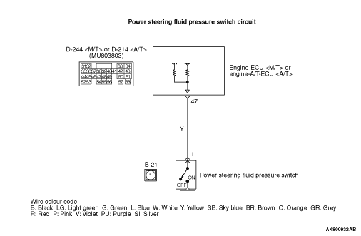
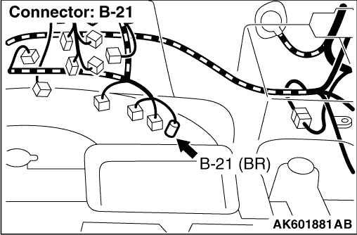

CONDITION
- The battery voltage is applied to the power steering fluid pressure switch
(terminal No. 1) from the engine-ECU <M/T> or engine-A/T-ECU <A/T> (terminal No. 47).
FUNCTION
- It is detected whether a load is applied on the power steering fluid pump
by steering or not, and the signal is inputted to the engine-ECU <M/T> or engine-A/T-ECU <A/T>.
When the power steering fluid pressure switch "ON" signal (a large load on the power steering
fluid pump) is inputted, the engine-ECU <M/T> or engine-A/T-ECU <A/T> provides the idle-up
control.
PROBABLE CAUSES
- Failed power steering fluid pressure switch
- Open/short circuit in power steering fluid pressure switch circuit or loose connector
contact
- Failed engine-ECU <M/T>
- Failed engine-A/T-ECU <A/T>
DIAGNOSIS PROCEDURE |
STEP 1. Connector check: B-21 power steering fluid pressure switch connector |
Q.
Is the check result normal?
|
 Go to Step 2 . Go to Step 2 . |
|
 Repair or replace the connector. Repair or replace the connector. |
|
STEP 2. Perform voltage measurement at B-21 power steering fluid pressure switch connector. |
|
| OK: System voltage |
Q.
Is the check result normal?
|
| Go to Step 8 . |
|
| Go to Step 3 . |
|
STEP 3. Perform voltage measurement at D-244 engine-ECU <M/T> connector or D-214 engine-A/T-ECU <A/T> connector. |
|
| OK: System voltage |
Q.
Is the check result normal?
|
| Go to Step 4 . |
|
| Go to Step 5 . |
|
STEP 4. Connector check: D-244 engine-ECU <M/T> connector or D-214 engine-A/T-ECU <A/T> connector |
Q.
Is the check result normal?
|
|
|
| Repair or replace the connector. |
|
STEP 5. Connector check: D-244 engine-ECU <M/T> connector or D-214 engine-A/T-ECU <A/T> connector |
Q.
Is the check result normal?
|
| Go to Step 6 . |
|
| Repair or replace the connector. |
|
STEP 6. Check harness between B-21 (terminal No. 1) power steering fluid pressure switch connector and D-244 (terminal No. 47) engine-ECU <M/T> connector or D-214 (terminal No. 47) engine-A/T-ECU <A/T> connector. |
|
Q.
Is the check result normal?
|
| Go to Step 7 . |
|
| Repair the damaged harness wire. |
|
STEP 7. M.U.T.-III data list |
|
Q.
Is the check result normal?
|
Intermittent malfunction (Refer to GROUP 00 - How to Use Troubleshooting/Inspection
Service Points - How to Cope with Intermittent Malfunctions  ). ). |
|
| Replace the engine-ECU <M/T> or engine-A/T-ECU <A/T>. |
|
STEP 8. Perform voltage measurement at D-244 engine-ECU <M/T> connector or D-214 engine-A/T-ECU <A/T> connector. |
|
OK:
1 V or less (Steering wheel: Turned) |
Q.
Is the check result normal?
|
| Go to Step 11 . |
|
| Go to Step 9 . |
|
STEP 9. Connector check: D-244 engine-ECU <M/T> connector or D-214 engine-A/T-ECU <A/T> connector |
Q.
Is the check result normal?
|
| Go to Step 10 . |
|
| Repair or replace the connector. |
|
STEP 10. Check harness between B-21 (terminal No. 1) power steering fluid pressure switch connector and D-244 (terminal No. 47) engine-ECU <M/T> connector or D-214 (terminal No. 47) engine-A/T-ECU <A/T> connector. |
|
Q.
Is the check result normal?
|
| Replace the power steering fluid pressure switch. |
|
| Repair the damaged harness wire. |
|
STEP 11. Connector check: D-244 engine-ECU <M/T> connector or D-214 engine-A/T-ECU <A/T> connector |
Q.
Is the check result normal?
|
| Go to Step 7 . |
|
| Repair or replace the connector. |
|