|
|
- Check for height of brake pedal (Refer to GROUP 35A - On-vehicle
Service - Brake Pedal Check And Adjustment
 ). ).
|
|
|
Q.
Is the check result normal?
|
|
|
Q.
Is the check result normal?
|
|
|
 Repair or replace the connector. Repair or replace the connector.
|
|
|
|
|
|
- Check the stop lamp switch (Refer to GROUP 35A - Brake Pedal - Inspection - Stop
Lamp Switch Check ).
|
|
|
Q.
Is the check result normal?
|
|
|
Replace the stop lamp switch.
|
|
|
|
|
|
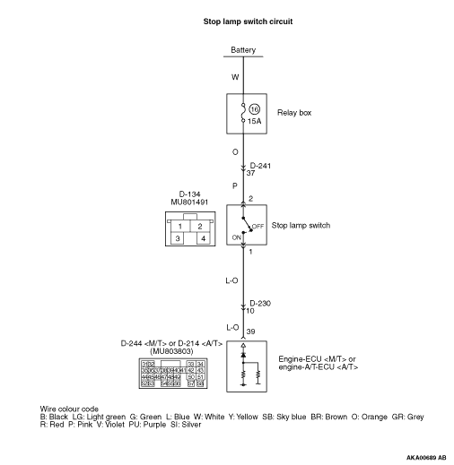
- Disconnect connector, and measure at harness side.
- Voltage between terminal No. 2 and earth.
|
|
|
Q.
Is the check result normal?
|
|
|
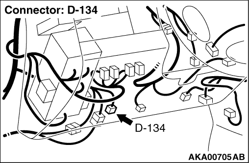
Check intermediate connector D-241, and repair
if necessary. If intermediate connector is normal, check and repair harness between D-134 (terminal
No. 2) stop lamp switch connector and battery.
- Check power supply line for open/short circuit.
|
|
|
|
|
|
Q.
Is the check result normal?
|
|
|
Repair or replace the connector.
|
|
|
|
|
|
- Disconnect connector, and measure at the harness side.
- Voltage between terminal No. 39 and the earth.
|
|
|
OK:
System voltage (Brake pedal: Depressed)
1 V or less (Brake pedal: Released)
|
|
|
Q.
Is the check result normal?
|
|
|
- Check output line for open/short circuit.
|
|
|
Q.
Is the check result normal?
|
|
|
 For a short circuit, check and repair harness and the connector for the stop lamp
switch output signal. For a short circuit, check and repair harness and the connector for the stop lamp
switch output signal.
|
|
|
|
|
|
Repair the damaged harness wire.
|
|
|
|
|
|
- Check output line for damage.
|
|
|
Q.
Is the check result normal?
|
|
|
Repair the damaged harness wire.
|
|
|
|
|
|
- Refer to Data List Reference Table .
- Item 74: Stop lamp switch
|
|
|
Q.
Is the check result normal?
|
|
|
Intermittent malfunction (Refer to GROUP 00 - How to Use Troubleshooting/Inspection
Service Points - How to Cope with Intermittent Malfunctions ).
|
|
|
|
|
|
Replace the engine-ECU <M/T> or engine-A/T-ECU <A/T>.
|
|
|
|