|
|
- Measure battery voltage during cranking.
|
|
|
Q.
Is the check result normal?
|
|
|
 Check battery (Refer to GROUP 54A - Battery - On-vehicle Service - Battery
test Check battery (Refer to GROUP 54A - Battery - On-vehicle Service - Battery
test  ). ).
|
|
|
|
|
|
Q.
Is the check result normal?
|
|
|
Repair or replace the connector.
|
|
|
|
|
|
- Check engine control relay (Refer to ).
|
|
|
Q.
Is the check result normal?
|
|
|
Replace the engine control relay.
|
|
|
|
|
|
- Remove relay, and measure at relay box side.
- Voltage between terminal No. 2 and earth, also between terminal No. 3 and earth.
|
|
|
Q.
Is the check result normal?
|
|
|
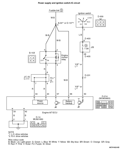
Check intermediate connector A-03*1 or
D-137*2, and repair if necessary. If intermediate connector is normal, check
and repair harness between B-15X (terminal No. 2 and terminal No. 3) engine control relay connector
and battery.
- Check power supply line for open/short circuit.
|
|
|
|
|
|
Q.
Is the check result normal?
|
|
|
Repair or replace the connector.
|
|
|
|
|
|
- Measure engine-A/T-ECU terminal voltage.
- Ignition switch: ON
- Voltage between terminal No. 34 and earth, also between terminal No. 43 and earth.
|
|
|
Q.
Is the check result normal?
|
|
|

Check and repair harness between B-15X (terminal No.
4) engine control relay connector and D-214 (terminal No. 57) engine-A/T-ECU connector.
- Check signal line for short circuit.
|
|
|
|
|
|
- Check power supply line for open/short circuit and damage.
|
|
|
Q.
Is the check result normal?
|
|
|
Repair the damaged harness wire.
|
|
|
|
|
|
- Disconnect connector, and measure at harness side.
- Ignition switch: ON
- Voltage between terminal No. 50 and earth.
|
|
|
Q.
Is the check result normal?
|
|
|
Q.
Is the check result normal?
|
|
|
Repair or replace the connector.
|
|
|
|
|
|
- Check ignition switch (Refer to GROUP 54A - Ignition Switch - Inspection ).
|
|
|
Q.
Is the check result normal?
|
|
|
Check intermediate connectors D-231, D-403
and D-405, and repair if necessary. If intermediate connectors are normal, check and repair
harness between D-309 (terminal No. 2) ignition switch connector and D-214 (terminal No. 50)
engine-A/T-ECU connector.
- Check output line for open/short circuit and damage.
|
|
|
|
|
|
Replace the ignition switch.
|
|
|
|
|
|
- Check output line for damage.
|
|
|
Q.
Is the check result normal?
|
|
|
Repair the damaged harness wire.
|
|
|
|
|
|
- Check power supply line for damage.
|
|
|
Q.
Is the check result normal?
|
|
|
Repair the damaged harness wire.
|
|
|
|
|
|
- Check output line for damage.
|
|
|
Q.
Is the check result normal?
|
|
|
Repair the damaged harness wire.
|
|
|
|
|
|
Q.
Is the check result normal?
|
|
|
Check and repair harness between D-214 engine-A/T-ECU
connector and D-14 earth connector.
- Check and repair harness between D-214 (terminal
No. 33) engine-A/T-ECU connector and D-14 (terminal No. 2) earth connector.
- Check and repair harness between D-214 (terminal No. 42) engine-A/T-ECU connector and
D-14 (terminal No. 1) earth connector.
- Check earthing line for open circuit and damage.
|
|
|
|
|
|
Repair or replace the connector.
|
|
|
|