|
|
Q.
Is the check result normal?
|
|
|
 Repair or replace the connector. Repair or replace the connector.
|
|
|
|
|
|
- Disconnect connector, and measure at harness side.
- Ignition switch: ON
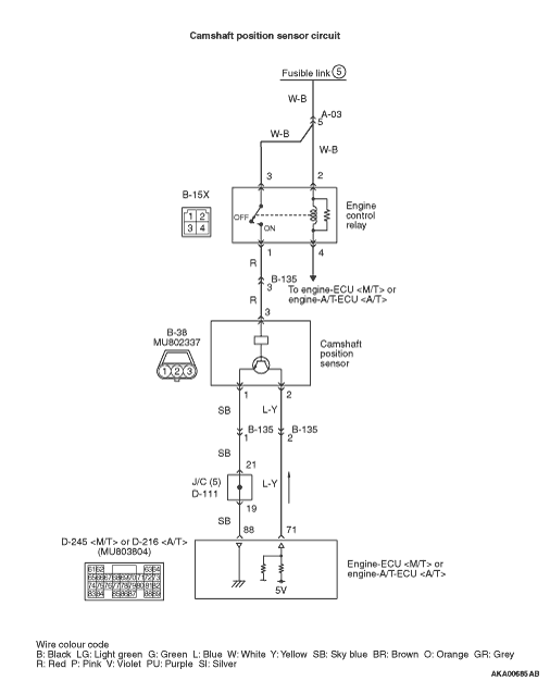
- Voltage between terminal No. 3 and earth.
|
|
|
Q.
Is the check result normal?
|
|
|
Q.
Is the check result normal?
|
|
|

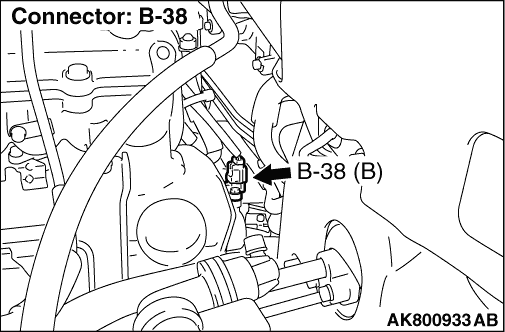
Check intermediate connector B-135, and repair if necessary. If intermediate connector is normal, check and repair harness between B-38 (terminal No. 3) camshaft position sensor connector and B-15X (terminal No. 1) engine control relay connector.
- Check power supply line for open/short circuit.
|
|
|
|
|
|
Repair or replace the connector.
|
|
|
|
|
|
- Disconnect connector, and measure at harness side.
- Ignition switch: ON
- Voltage between terminal No. 2 and earth.
|
|
|
Q.
Is the check result normal?
|
|
|
- Measure engine-ECU <M/T> or engine-A/T-ECU <A/T> terminal voltage.
- Disconnect B-38 camshaft position sensor connector.
- Ignition switch: ON
- Voltage between terminal No. 71 and earth.
|
|
|
Q.
Is the check result normal?
|
|
|
Q.
Is the check result normal?
|
|
|
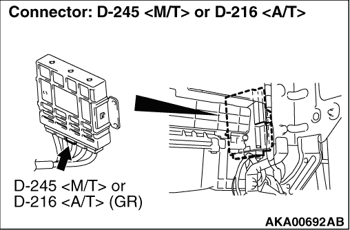
Check intermediate connector B-135, and repair if necessary. If intermediate connector is normal, check and repair harness between B-38 (terminal No. 2) camshaft position sensor connector and D-245 (terminal No. 71) engine-ECU <M/T> connector or D-216 (terminal No. 71) engine-A/T-ECU <A/T> connector.
- Check output line for open circuit.
|
|
|
|
|
|
Repair or replace the connector.
|
|
|
|
|
|
Q.
Is the check result normal?
|
|
|
Repair or replace the connector.
|
|
|
|
|
|
- Check output line for short circuit.
|
|
|
Q.
Is the check result normal?
|
|
|
Repair the damaged harness wire.
|
|
|
|
|
|
Q.
Does trouble symptom persist?
|
|
|
Replace the engine-ECU <M/T> or engine-A/T-ECU <A/T>.
|
|
|
|
|
|
Intermittent malfunction (Refer to GROUP 00 - How to Use Troubleshooting/Inspection Service Points - How to Cope with Intermittent Malfunctions  ). ).
|
|
|
|
|
|
- Disconnect connector, and measure at harness side.
- Resistance between terminal No. 1 and earth.
|
|
|
OK: Continuity (2 Ω or less)
|
|
|
Q.
Is the check result normal?
|
|
|
Q.
Is the check result normal?
|
|
|
Repair or replace the connector.
|
|
|
|
|
|
- Check earthing line for open circuit and damage.
|
|
|
Q.
Is the check result normal?
|
|
|
Repair the damaged harness wire.
|
|
|
|
|
|
- Use special tool test harness (MB991709) to connect connector, and measure at pick-up harness.
- Engine: Idling
- Transmission: Neutral <M/T> or P range <A/T>
- Voltage between terminal No. 2 and earth.
|
|
|
OK: Waveforms should be displayed on Inspection procedure using an oscilloscope (Refer to ), its maximum value should be 4.8 V or more, and its minimum value should be 0.6 V or less with no noise in waveform.
|
|
|
Q.
Is the check result normal?
|
|
|
Q.
Is the check result normal?
|
|
|
Repair or replace the connector.
|
|
|
|
|
|
- Check power supply line for damage.
|
|
|
Q.
Is the check result normal?
|
|
|
Repair the damaged harness wire.
|
|
|
|
|
|
Q.
Is the check result normal?
|
|
|
Repair or replace the connector.
|
|
|
|
|
|
- Check output line for damage.
|
|
|
Q.
Is the check result normal?
|
|
|
Repair the damaged harness wire.
|
|
|
|
|
|
- Check earthing line for damage.
|
|
|
Q.
Is the check result normal?
|
|
|
Repair the damaged harness wire.
|
|
|
|
|
|
Q.
Is the check result normal?
|
|
|
Replace the camshaft position sensing cylinder.
|
|
|
|
|
|
Q.
Does trouble symptom persist?
|
|
|
Replace the camshaft position sensor.
|
|
|
|
|
|
Intermittent malfunction (Refer to GROUP 00 - How to Use Troubleshooting/Inspection Service Points - How to Cope with Intermittent Malfunctions ).
|
|
|
|