Code No. P0622: Alternator FR Terminal System
OPERATION
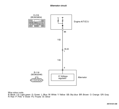
- The energised state of the alternator field coil is inputted from the alternator (terminal No. 4) to the engine-A/T-ECU (terminal No. 86).
FUNCTION
- A signal of the power supply duty ratio for the alternator field coil is inputted to the engine-A/T-ECU.
- In response to the signal, the engine-A/T-ECU detects the alternator output current and controls the idling speed according to the output current (electric load).
TROUBLE JUDGMENT
Check Condition
- The engine speed is more than approximately 500 r/min.
- Input voltage from the alternator FR terminal is approximately battery voltage for 20 seconds.
PROBABLE CAUSES
- Failed alternator
- Open circuit in alternator FR terminal circuit or loose connector
- Failed engine-A/T-ECU
DIAGNOSIS PROCEDURE |
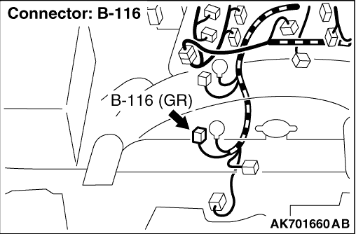
STEP 1. Connector check: B-116 alternator connector |
Q.
Is the check result normal?
|
 Go to Step 2. Go to Step 2. |
|
 Repair or replace the connector. Repair or replace the connector. |
|
STEP 2. Perform voltage measurement at B-116 alternator connector. |
|
| OK: System voltage |
Q.
Is the check result normal?
|
| Go to Step 6. |
|
| Go to Step 3. |
|
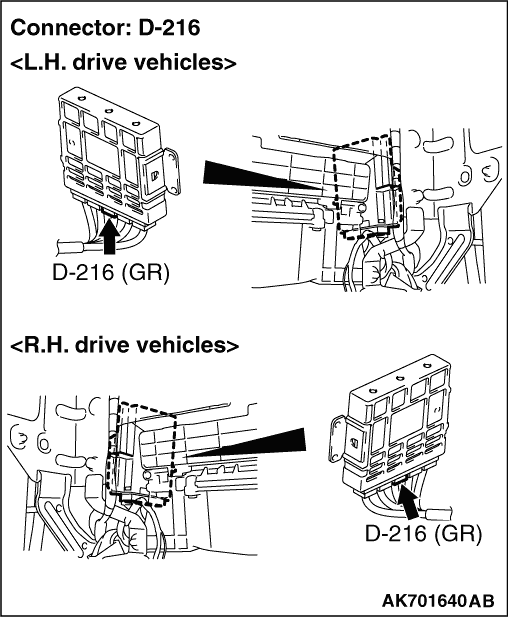
STEP 3. Connector check: D-216 engine-A/T-ECU connector. |
Q.
Is the check result normal?
|
| Go to Step 4. |
|
| Repair or replace the connector. |
|
STEP 4. Check harness between B-116 (terminal No. 4) alternator connector and D-216 (terminal No. 86) engine-A/T-ECU connector. |
|
|
Q.
Is the check result normal?
|
| Go to Step 5. |
|
| Repair the damaged harness wire. |
|
STEP 5. M.U.T.-III diagnosis code |
|
Q.
Is the diagnosis code set?
|
| Replace the engine-A/T-ECU. |
|
Intermittent malfunction (Refer to GROUP 00 - How to Use Troubleshooting/Inspection Service Points - How to Cope with Intermittent Malfunctions  ). ). |
|
STEP 6. Connector check: D-216 engine-A/T-ECU connector |
Q.
Is the check result normal?
|
| Go to Step 7. |
|
| Repair or replace the connector. |
|
STEP 7. Check harness between B-116 (terminal No. 4) alternator connector and D-216 (terminal No. 86) engine-A/T-ECU connector. |
|
|
Q.
Is the check result normal?
|
| Go to Step 8. |
|
| Repair the damaged harness wire. |
|
STEP 8. Perform voltage measurement at D-216 engine-A/T-ECU connector. |
|
| OK: Switching the headlamps to ON from OFF causes the voltage to fall. |
Q.
Is the check result normal?
|
| Go to Step 5. |
|
| Replace the alternator. |
|