Code No. P0122: Throttle Position Sensor (Main) Circuit Low Input
OPERATION
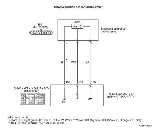
- A power voltage of 5 V is applied to the electronic-controlled
throttle valve (terminal No. 2) from the engine-ECU <M/T> or engine-A/T-ECU <A/T> (terminal
No. 106).
- The power voltage is earthed to the engine-ECU <M/T> or engine-A/T-ECU <A/T>
(terminal No. 105) from the electronic-controlled throttle valve (terminal No. 4).
- The sensor signal is inputted to the engine-ECU <M/T> or engine-A/T-ECU <A/T>
(terminal No. 115) from the electronic-controlled throttle valve output terminal (terminal No.
1).
FUNCTION
- The throttle position sensor converts the throttle valve
position into voltage and inputs it into the engine-ECU <M/T> or engine-A/T-ECU <A/T>.
- The engine-ECU <M/T> or engine-A/T-ECU <A/T> controls the throttle valve
position.
TROUBLE JUDGMENT
Check Condition
- Ignition switch is in "ON" position.
- Throttle position sensor (main) output voltage is 0.35 V or less.
PROBABLE CAUSES
- Failed throttle position sensor (main)
- Open/short circuit in throttle position sensor circuit or loose connector contact
- Failed engine-ECU <M/T> or engine-A/T-ECU <A/T>
DIAGNOSIS PROCEDURE |
STEP 1. M.U.T.-III data list |
|
Q.
Is the check result normal?
|
 Intermittent malfunction (Refer to GROUP 00 - How to Use Troubleshooting/Inspection
Service Points - How to Cope with Intermittent Malfunctions Intermittent malfunction (Refer to GROUP 00 - How to Use Troubleshooting/Inspection
Service Points - How to Cope with Intermittent Malfunctions  ). ). |
|
 Go to Step 2 . Go to Step 2 . |
|
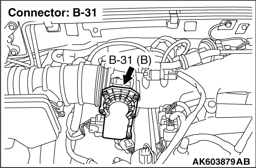
STEP 2. Connector check: B-31 electronic-controlled throttle valve connector |
Q.
Is the check result normal?
|
| Go to Step 3 . |
|
| Repair or replace the connector. |
|
STEP 3. Perform voltage measurement at B-31 electronic-controlled throttle valve connector. |
|
| OK: 4.9 - 5.1 V |
Q.
Is the check result normal?
|
| Go to Step 7 . |
|
| Go to Step 4 . |
|
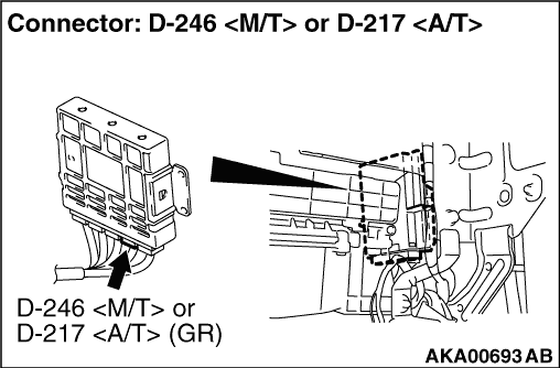
STEP 4. Connector check: D-246 engine-ECU <M/T> connector or D-217 engine-A/T-ECU <A/T> connector |
Q.
Is the check result normal?
|
| Go to Step 5 . |
|
| Repair or replace the connector. |
|
STEP 5. Check harness between B-31 (terminal No. 2) electronic-controlled throttle valve connector and D-246 (terminal No. 106) engine-ECU <M/T> connector or D-217 (terminal No. 106) engine-A/T-ECU <A/T> connector. |
|
Q.
Is the check result normal?
|
| Go to Step 6 . |
|
| Repair the damaged harness wire. |
|
STEP 6. M.U.T.-III data list |
|
Q.
Is the check result normal?
|
| Intermittent malfunction (Refer to GROUP 00 - How to Use Troubleshooting/Inspection
Service Points - How to Cope with Intermittent Malfunctions ). |
|
| Replace the engine-ECU <M/T> or engine-A/T-ECU <A/T>. |
|
STEP 7. Connector check: D-246 engine-ECU <M/T> connector or D-217 engine-A/T-ECU <A/T> connector |
Q.
Is the check result normal?
|
| Go to Step 8 . |
|
| Repair or replace the connector. |
|
STEP 8. Check harness between B-31 (terminal No. 2) electronic-controlled throttle valve connector and D-246 (terminal No. 106) engine-ECU <M/T> connector or D-217 (terminal No. 106) engine-A/T-ECU <A/T> connector. |
|
Q.
Is the check result normal?
|
| Go to Step 9 . |
|
| Repair the damaged harness wire. |
|
STEP 9. Check harness between B-31 (terminal No. 1) electronic-controlled throttle valve connector and D-246 (terminal No. 115) engine-ECU <M/T> connector or D-217 (terminal No. 115) engine-A/T-ECU <A/T> connector. |
|
Q.
Is the check result normal?
|
| Go to Step 10 . |
|
| Repair the damaged harness wire. |
|
STEP 10. Replace the electronic-controlled throttle valve |
|
Q.
Is the check result normal?
|
| Check end. |
|
| Replace the engine-ECU <M/T> or engine-A/T-ECU <A/T>. |
|