Code No. P2100: Throttle Valve Control Servo Circuit (open)


OPERATION


  • Controls the current that is applied from the engine-ECU <M/T> or engine-A/T-ECU <A/T> (terminals No. 133, No. 141) to the electronic-controlled throttle valve (terminals No. 5, No. 6).

FUNCTION


  • Engine-ECU <M/T> or engine-A/T-ECU <A/T> varies the direction and the amperage of the current that is applied to the throttle valve control servo in order to control the opening of the throttle valve.

TROUBLE JUDGMENT


Check Condition
  • Battery positive voltage is 8.3 V or higher.
Judgement Criteria
  • The proposed output voltage subtracted from the output voltage of the (main/sub) throttle position sensor equals 0.1 V or higher.
  • The learning value at the middle-opened degree subtracted from the output voltage of the (main/sub) throttle position sensor equals 0.2 V or lower.
  • Although the driving signal of the throttle valve control servo is output, the throttle valve control servo is not driven.

PROBABLE CAUSES


  • Failed throttle valve control servo.
  • Open circuit in throttle valve control servo circuit or loose connector contact.
  • Failed engine-ECU <M/T> or engine-A/T-ECU <A/T>

DIAGNOSIS PROCEDURE


STEP 1. Connector check: B-31 electronic-controlled throttle valve connector


Q. Is the check result normal?

Go to Step 2 .
Repair or replace the connector.

STEP 2. Perform resistance measurement at B-31 electronic-controlled throttle valve connector.


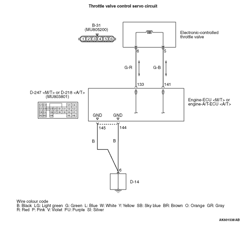
  • Disconnect connector, and measure at electronic-controlled throttle valve side.
  • Resistance between terminal No. 5 and No. 6.
OK: 0.3 - 100 kΩ (at 20 °C)

Q. Is the check result normal?

Go to Step 3 .
Replace the throttle body assembly.

STEP 3. Connector check: D-247 engine-ECU <M/T> connector or D-218 engine-A/T-ECU <A/T> connector


Q. Is the check result normal?

Go to Step 4 .
Repair or replace the connector.

STEP 4. Perform resistance measurement at D-247 engine-ECU <M/T> connector or D-218 engine-A/T-ECU <A/T> connector.


  • Disconnect connector and measure at harness side.
  • Resistance between terminal No. 144, No. 145 and earth.
OK: Continuity (2 Ω or less)

Q. Is the check result normal?

Go to Step 6 .
Go to Step 5 .

STEP 5. Connector check: D-14 earth connector


Q. Is the check result normal?


    Check and repair harness between engine-ECU <M/T> connector or engine-A/T-ECU <A/T> connector and earth connector.

  1. Check harness between D-247 (terminal No. 144) engine-ECU <M/T> connector or D-218 (terminal No. 144) engine-A/T-ECU <A/T> connector and D-14 (terminal No. 6) earth connector.
  2. Check harness between D-247 (terminal No. 145) engine-ECU <M/T> connector or D-218 (terminal No. 145) engine-A/T-ECU <A/T> connector and D-14 (terminal No. 6) earth connector.

  • Check earthing line for open circuit and damage.
Repair or replace the connector.

STEP 6. Check harness between B-31 (terminal No. 6) electronic-controlled throttle valve connector and D-247 (terminal No. 133) engine-ECU <M/T> connector or D-218 (terminal No. 133) engine-A/T-ECU <A/T> connector.


  • Check output line for open circuit and damage.

Q. Is the check result normal?

Go to Step 7 .
Repair the damaged harness wire.

STEP 7. Check harness between B-31 (terminal No. 5) electronic-controlled throttle valve connector and D-247 (terminal No. 141) engine-ECU <M/T> connector or D-218 (terminal No. 141) engine-A/T-ECU <A/T> connector.


  • Check output line for open circuit and damage.

Q. Is the check result normal?

Go to Step 8
Repair the damaged harness wire.

STEP 8. Check the trouble symptoms.


Q. Is the diagnosis code set?

Replace the engine-ECU <M/T> or engine-A/T-ECU <A/T>.
Intermittent malfunction (Refer to GROUP 00 - How to Use Troubleshooting/Inspection Service Points - How to Cope with Intermittent Malfunctions ).