Code No. P2138: Accelerator Pedal Position Sensor (Main and Sub) Range/Performance Problem
OPERATION
- Refer to Code No. P2122: Accelerator Pedal Position Sensor
(main) Circuit Low Input
 .
. - Refer to Code No. P2127: Accelerator Pedal Position Sensor (sub) Circuit Low Input .
FUNCTION
- Engine-ECU <M/T> or engine-A/T-ECU <A/T> checks
the accelerator pedal position sensor output signal characteristics for abnormal conditions.
TROUBLE JUDGMENT
Check Conditions
- Ignition switch is in ON position
- Accelerator pedal position sensor (main) output voltage is 0.2 - 4.8 V.
- Accelerator pedal position sensor (sub) output voltage is 0.2 - 4.8 V.
- Change of accelerator pedal position sensor (sub) output voltage per 25 milliseconds
is lower than 0.06 V.
- The difference is 0.3 V or more between the output voltages multiplied by two of
the sub accelerator pedal position sensor and the output voltage of the main accelerator pedal
position sensor.
PROBABLE CAUSES
- Failed accelerator pedal position sensor
- Harness damage in accelerator pedal position sensor circuit or loose connector contact
- Failed engine-ECU <M/T> or engine-A/T-ECU <A/T>
DIAGNOSIS PROCEDURE |
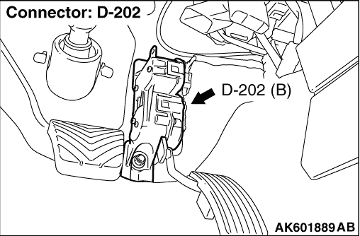
STEP 1. Connector check: D-202 accelerator pedal position sensor connector |
Q.
Is the check result normal?
|
 Go to Step 2 . Go to Step 2 . |
|
 Repair or replace the connector. Repair or replace the connector. |
|
STEP 2. Perform resistance measurement at D-202 accelerator pedal position sensor connector. |
|
| OK: Continuity (2 Ω or less) |
Q.
Is the check result normal?
|
| Go to Step 6 . |
|
| Go to Step 3 . |
|
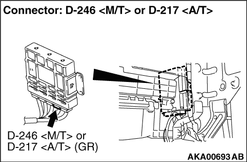
STEP 3. Connector check: D-246 engine-ECU <M/T> connector or D-217 engine-A/T-ECU <A/T> connector |
Q.
Is the check result normal?
|
| Go to Step 4 . |
|
| Repair or replace the connector. |
|
STEP 4. Check harness between D-202 (terminal No. 2) accelerator pedal position sensor connector and D-246 (terminal No. 91) engine-ECU <M/T> connector or D-217 (terminal No. 91) engine-A/T-ECU <A/T> connector. |
|
Q.
Is the check result normal?
|
| Go to Step 5 . |
|
| Repair the damaged harness wire. |
|
STEP 5. Check the trouble symptoms |
Q.
Does trouble symptom persist?
|
| Replace the engine-ECU <M/T> or engine-A/T-ECU <A/T>. |
|
| Intermittent malfunction (Refer to GROUP 00 - How to Use Troubleshooting/Inspection
Service Points - How to Cope with Intermittent Malfunctions ). |
|
STEP 6. Perform resistance measurement at D-202 accelerator pedal position sensor connector. |
|
| OK: Continuity (2 Ω or less) |
Q.
Is the check result normal?
|
| Go to Step 9 . |
|
| Go to Step 7 . |
|
STEP 7. Connector check: D-246 engine-ECU <M/T> connector or D-217 engine-A/T-ECU <A/T> connector |
Q.
Is the check result normal?
|
| Go to Step 8 . |
|
| Repair or replace the connector. |
|
STEP 8. Check harness between D-202 (terminal No. 5) accelerator pedal position sensor connector and D-246 (terminal No. 120) engine-ECU <M/T> connector or D-217 (terminal No. 120) engine-A/T-ECU <A/T> connector. |
|
Q.
Is the check result normal?
|
| Go to Step 5 . |
|
| Repair the damaged harness wire. |
|
STEP 9. Connector check: D-246 engine-ECU <M/T> connector or D-217 engine-A/T-ECU <A/T> connector |
Q.
Is the check result normal?
|
| Go to Step 10 . |
|
| Repair or replace the connector. |
|
STEP 10. Check harness between D-202 (terminal No. 1) accelerator pedal position sensor connector and D-246 (terminal No. 92) engine-ECU <M/T> connector or D-217 (terminal No. 92) engine-A/T-ECU <A/T> connector. |
|
Q.
Is the check result normal?
|
| Go to Step 11 . |
|
| Repair the damaged harness wire. |
|
STEP 11. Check harness between D-202 (terminal No. 4) accelerator pedal position sensor connector and D-246 (terminal No. 102) engine-ECU <M/T> connector or D-217 (terminal No. 102) engine-A/T-ECU <A/T> connector. |
|
Q.
Is the check result normal?
|
| Go to Step 12 . |
|
| Repair the damaged harness wire. |
|
STEP 12. Check harness between D-202 (terminal No. 3) accelerator pedal position sensor connector and D-246 (terminal No. 114) engine-ECU <M/T> connector or D-217 (terminal No. 114) engine-A/T-ECU <A/T> connector. |
|
Q.
Is the check result normal?
|
| Go to Step 13 . |
|
| Repair the damaged harness wire. |
|
STEP 13. Check harness between D-202 (terminal No. 6) accelerator pedal position sensor connector and D-246 (terminal No. 107) engine-ECU <M/T> connector or D-217 (terminal No. 107) engine-A/T-ECU <A/T> connector |
|
Q.
Is the check result normal?
|
| Go to Step 14 . |
|
| Repair the damaged harness wire. |
|
STEP 14. Replace the accelerator pedal assembly |
|
Q.
Is the check result normal?
|
| Check end. |
|
| Replace the engine-ECU <M/T> or engine-A/T-ECU <A/T>. |
|