Code No. P0161: Left bank Oxygen Sensor (Rear) Heater System


OPERATION
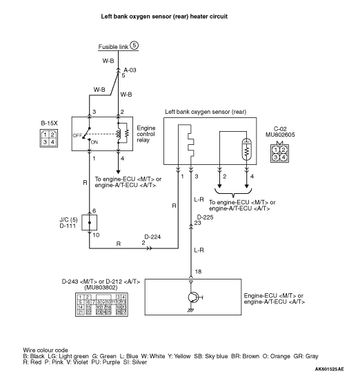
- Power is supplied to the heater power terminal (terminal
No. 1) of the left bank oxygen sensor (rear) connector from the engine control relay (terminal
No. 1).
- The heater (terminal No. 3) of the left bank oxygen sensor (rear) connector is controlled
by the power transistor in the engine-ECU <M/T> or engine-A/T-ECU <A/T> (terminal No.
18).
FUNCTION
- The power supply to the left bank oxygen sensor (rear)
heater is controlled by the ON/OFF control of the power transistor in the engine-ECU <M/T> or
engine-A/T-ECU <A/T>.
- Heating the left bank oxygen sensor (rear) heater enables the left bank oxygen sensor
(rear) to provide good response even when the exhaust emission temperature is low.
TROUBLE JUDGMENT
Check Conditions
- Engine coolant temperature is 20°C or higher.
- Battery positive voltage is 11 - 16 V.
- The engine speed is 500 r/min or more.
- Left bank oxygen sensor (rear) heater currents have continued to be 0.2 A or lower,
or 7.5 A or higher for 4 seconds.
PROBABLE CAUSES
- Failed left bank oxygen sensor (rear) heater
- Open/short circuit in left bank oxygen sensor (rear) heater circuit or loose connector
contact
- Failed engine-ECU <M/T> or engine-A/T-ECU <A/T>
DIAGNOSIS PROCEDURE |
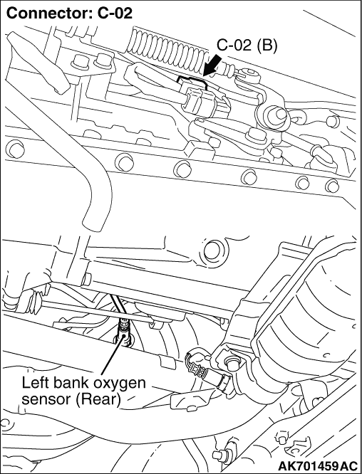
STEP 1. Connector check: C-02 left bank oxygen sensor (rear) connector |
Q.
Is the check result normal?
|
 Go to Step 2 . Go to Step 2 . |
|
 Repair or replace the connector. Repair or replace the connector. |
|
STEP 2. Perform resistance measurement at C-02 left bank oxygen sensor (rear) connector. |
|
| OK: 11 - 18 Ω |
Q.
Is the check result normal?
|
| Go to Step 3 . |
|
| Replace the left bank oxygen sensor (rear). |
|
STEP 3. Perform voltage measurement at C-02 left bank oxygen sensor (rear) connector. |
|
| OK: System voltage |
Q.
Is the check result normal?
|
| Go to Step 5 . |
|
| Go to Step 4 . |
|
STEP 4. Connector check: B-15X engine control relay connector |
Q.
Is the check result normal?
|
|
|
| Repair or replace the connector. |
|
STEP 5. Perform voltage measurement at D-243 engine-ECU <M/T> connector or D-212 engine-A/T-ECU <A/T> connector. |
|
| OK: System voltage |
Q.
Is the check result normal?
|
| Go to Step 8 . |
|
| Go to Step 6 . |
|
STEP 6. Connector check: D-243 engine-ECU <M/T> connector or D-212 engine-A/T-ECU <A/T> connector |
Q.
Is the check result normal?
|
| Go to Step 7 . |
|
| Repair or replace the connector. |
|
STEP 7. Check harness between C-02 (terminal No. 3) left bank oxygen sensor (rear) connector and D-243 (terminal No. 18) engine-ECU <M/T> connector or D-212 (terminal No. 18) engine-A/T-ECU <A/T> connector. |
|
|
Q.
Is the check result normal?
|
| Replace the engine-ECU <M/T> or engine-A/T-ECU <A/T>. |
|
| Repair the damaged harness wire. |
|
STEP 8. Connector check: D-243 engine-ECU <M/T> connector or D-212 engine-A/T-ECU <A/T> connector |
Q.
Is the check result normal?
|
| Go to Step 9 . |
|
| Repair or replace the connector. |
|
STEP 9. Check harness between C-02 (terminal No. 1) left bank oxygen sensor (rear) connector and B-15X (terminal No. 1) engine control relay connector. |
|
|
Q.
Is the check result normal?
|
| Go to Step 10 . |
|
| Repair the damaged harness wire. |
|
STEP 10. Check harness between C-02 (terminal No. 3) left bank oxygen sensor (rear) connector and D-243 (terminal No. 18) engine-ECU <M/T> connector or D-212 (terminal No. 18) engine-A/T-ECU <A/T> connector. |
|
|
Q.
Is the check result normal?
|
| Go to Step 11 . |
|
| Repair the damaged harness wire. |
|
STEP 11. M.U.T.-III diagnosis code. |
|
Q.
Is the diagnosis code set?
|
| Replace the engine-ECU <M/T> or engine-A/T-ECU <A/T>. |
|
Intermittent malfunction (Refer to GROUP 00 - How to Use Troubleshooting/Inspection
Service Points - How to Cope with Intermittent Malfunctions  ). ). |
|