Code No. P0103: Air Flow Sensor Circuit High Input
OPERATION
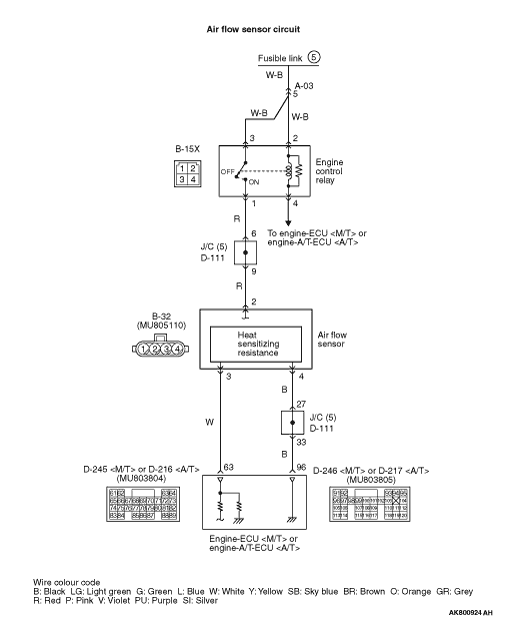
- Power is supplied by the engine control relay (terminal
No. 3) to the air flow sensor (terminal No. 2), and the air flow sensor (terminal No. 4) is earthed
through the engine-ECU <M/T> or engine-A/T-ECU <A/T> (terminal No. 96).
- The air flow sensor (terminal No. 3) outputs a sensor signal, which is input into
the engine-ECU <M/T> or engine-A/T-ECU <A/T> (terminal No. 63).
FUNCTION
- The air flow sensor outputs current that varies in accordance
with the intake air volume.
- In response to the signal, the engine-ECU <M/T> or engine-A/T-ECU <A/T>
controls exhaust gas recirculation control, etc.
TROUBLE JUDGMENT
Check Condition
- 3 seconds later after the ignition switch has been in "ON" position.
- The air flow sensor output voltage is 4.9 V or more for 2 second.
PROBABLE CAUSES
- Failed air flow sensor
- Open circuit or harness damage in air flow sensor circuit or loose connector contact
- Failed engine-ECU <M/T> or engine-A/T-ECU <A/T>
DIAGNOSIS PROCEDURE |
STEP 1. M.U.T.-III data list |
|
Q.
Is the check result normal?
|
 Intermittent malfunction (Refer to GROUP 00 - How to Use Troubleshooting/Inspection
Service Points - How to Cope with Intermittent Malfunctions Intermittent malfunction (Refer to GROUP 00 - How to Use Troubleshooting/Inspection
Service Points - How to Cope with Intermittent Malfunctions  ). ). |
|
 Go to Step 2 . Go to Step 2 . |
|
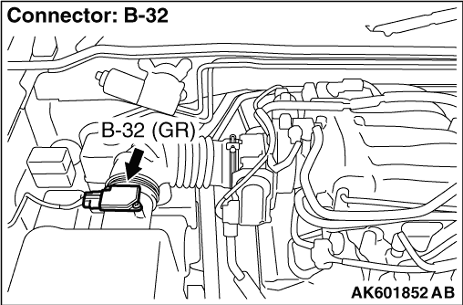
STEP 2. Connector check: B-32 air flow sensor connector |
Q.
Is the check result normal?
|
| Go to Step 3 . |
|
| Repair or replace the connector. |
|
STEP 3. Perform resistance measurement at B-32 air flow sensor connector. |
|
| OK: Continuity (2 Ω or less) |
Q.
Is the check result normal?
|
| Go to Step 7 . |
|
| Go to Step 4 . |
|
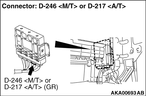
STEP 4. Connector check: D-246 engine-ECU <M/T> connector or D-217 engine-A/T-ECU <A/T> connector |
Q.
Is the check result normal?
|
| Go to Step 5 . |
|
| Repair or replace the connector. |
|
STEP 5. Check harness between B-32 (terminal No. 4) air flow sensor connector and D-246 (terminal No. 96) engine-ECU <M/T> connector or D-217 (terminal No. 96) engine-A/T-ECU <A/T> connector. |
|
|
Q.
Is the check result normal?
|
| Go to Step 6 . |
|
| Repair the damaged harness wire. |
|
STEP 6. M.U.T.-III data list |
|
Q.
Is the check result normal?
|
| Intermittent malfunction (Refer to GROUP 00 - How to Use Troubleshooting/Inspection
Service Points - How to Cope with Intermittent Malfunctions ). |
|
| Replace the engine-ECU <M/T> or engine-A/T-ECU <A/T>. |
|
STEP 7. M.U.T.-III data list |
|
Q.
Is the check result normal?
|
| Intermittent malfunction (Refer to GROUP 00 - How to Use Troubleshooting/Inspection
Service Points - How to Cope with Intermittent Malfunctions ). |
|
| Go to Step 8 . |
|
STEP 8. Replace the air flow sensor |
|
Q.
Is the diagnosis code set?
|
| Replace the engine-ECU <M/T> or engine-A/T-ECU <A/T>. |
|
| Check end. |
|